12
46-622 Series 3 Liquid Level Switches ASME B31.3 Construction
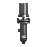
Inspection of the interior of the chamber is possible on
flanged cage models. To do this, the control head must be
removed to provide proper access to the chamber. This
procedure will assure that the head assembly is removed
and reinstalled properly.
1. Allow vessel to get to safe temperature and pressure before
opening the pressure boundary.
2. Power down all wiring to the unit.
3. Remove all wiring and conduit from the unit.
4. Remove flange bolts.
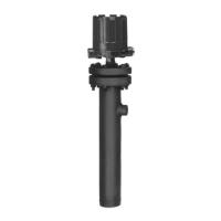
5. Prepare an area where the head assembly can be placed
such that it rests on the flange in its normal orientation
(two 2×4 boards placed across an open drum work well).
Refer to
.
6. Carefully lift the head assembly by holding the sides of the
flange. Maintain the head assembly as much as possible in
the vertical position.
NOTE: Care must be taken not to place side force on the float which
could bend the stem.
7. With the unit resting in its temporary fixture in an upright
position, it can now be inspected or repaired.
Do not place the unit on its side — this could result in
damage to the stem.
 Loading...