46-622 Series 3 Liquid Level Switches ASME B31.3 Construction
5
2.2 Critical Alarm Function
It is recommended that for critical alarm functions, an
additional level switch be installed as a high–high or low–
low level alarm for maximum protection.
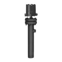
2.3 Piping
shows a typical piping installation of a
Magnetrol Series 3 control to a pressure vessel. Level decals
on control identify the actuation levels for the bottom
switch mechanism of a unit with three switches at mini-
mum specific gravity. Charts defining actuation levels for a
unit with one switch at different specific gravities can be
found on pages 23–24, Actuating Levels and Specific
Gravities, Section 5.2.3.
Use pipe of sufficient strength to support the control. If
necessary, provide a stand or hanger to help support its
weight. All piping should be straight and free of “low
spots” or “pockets” so that lower liquid line will drain
towards the vessel and upper vapor line will drain toward
the control. Shut-off valves are recommended for installa-
tion between the vessel and the control. If control is to be
used with a low temperature liquid (one which will “boil”
in the float chamber if outside heat is absorbed), the
chamber and piping should be insulated. Such boiling
in the chamber will cause false level indications.
DO NOT INSULATE SWITCH MECHANISM
HOUSING.
On controls equipped with pneumatic switch assemblies,
consult bulletin on mechanism furnished for air (or gas)
piping instructions. Refer to the Switch Instruction
Reference Bulletins chart on page 7 to find bulletin
numbers for pneumatic switches.
2.4 Mounting
If equipment is used in a manner not specified by the
manufacturer, protection provided by the equipment may
be impaired.
This instrument is intended for use in Installation
Category II, Pollution Degree 2.
Adjust piping as required to bring control to a vertical
position. Magnetrol controls must be mounted within 3°
of vertical. A 3° slant is noticeable by eye, but installation
should be checked with a spirit level on top and/or sides of
float chamber.
S
hutoff
valve
D
rain
valve
Conduit
outlet
Switch
actuating
l
evel
reference
marks
M
ax. 12"
Pressure
vessel
 Loading...