12
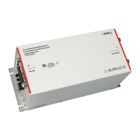
CDN HSS-2
4.3. Power over Ethernet (PoE)
TheCDNHSS-2allowstheuseofthePoweroverEthernet(PoE)function.Incasethehandshakeprocedurefails,
alljumpersneedstoberemovedfromtheCDNHSS-2.Thejumpersneedtobereplacedafterestablishment
of a successful PoE connection for proceeding the surge testing.
4.4. One pair (two lines) application with DC and LF
All applications with coupling to one pair (two lines) only allowed with absence of DC and low frequency signals
below10KHz.ThesignalswillbeshortedbytheinternalZ-chokesoftheCDNHSS-2.Teseqrecommendsthe
usofCDN118forthisapplication,even10/700μspulseswithupto6kVcanbeapplied.
5. VERIFICATION
5.1. Voltage
Thepulsespecicationcanbeveriedwiththefollowingsetups.TheAE-andEUT-sideoftheCDNHSS-2need
tobeconnectedinthecommonmodefortherequestedapplication.Anoscilloscopewitha1MΩinputis
connectedviaa1/1000dividerwiththeEUT-sideoftheCDNHSS-2.Thepulseconnectionsfromthesurge
generatorispluggedintotheHVsocketoftheCDNHSS-2.
The jumper setting for selecting the coupling path is required in relation to the application.
Common mode adapter
as required for the application
Shorted Ground
plane
Divider
1/1000
1 MΩ input
AE port EUT port
Surge input
CDN HSS
Jumper settings
as required for
the application
Short circuit connector
SURGE GENERATOR
EUT Power
Output
Surge
Output
High Low
Power on
Pulse
High voltage active
EUT-Power on
Error
Burst
Output
1
10
100
NSG 3040
OSCILLOSCOPE
Channel 1 Channel 2 Channel 3 Channel 4
USB
USB
Power
Tuning
Back
0
.
1
4
7 8
5
2
3
kHz
dBm
6
9
MHz
dBµV
Hz
V
Enter
StSizeStSize StSize
Step
1
Step
2
Step
3
DIA
MEAS
FOR
DIS
SCL
TRA
STO
FRQ
LVL
RCL
MOD
MOD
STO
CH 1
CH 2
RCL
STO
FRQ
LVL
RCL
MOD
MOD
Stop
Run
Hold
STO
FRQ
LVL
RCL
MOD
MOD
Local
2nd
Help
RF
ON/OFF
Figure 12: Example of a setup for verifying the pulse parameters with measuring the open-
circuit voltage

 Loading...