Versitron Operation Manual 31
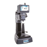
3. Front-to-Back centering is adjusted by the set screw and nut underneath the anvil
stage.
4. Loosen anvil plate knob.
5. Slide the stand forward on bench until the elevating screw is slightly over the
edge to work on screw and nut located on the underside of anvil plate. (Be
careful not to allow tester to tip over.)
6. Loosen the locking nut.
7. Turn screw up (clockwise) to move the anvil forward, down to move the anvil
back.
8. Check alignment again after tightening the locking nut and anvil plate knob. Do
not use excessive force.
An alternate alignment method is to tighten or loosen anvil plate knob using the special
wrench provided. This permits minor small Vee anvil adjustments to be made quickly.
T-Stand Vee Anvil adjustment: front-to-back
(underside view)
T-Stand Vee Anvil adjustment: side-to-side
Head Carriage
Height-Adjustment
Knob
Locking Nut
(left side)
Locking Knob
Elevating Screw
Adjustment Screw &
Lock Nut
 Loading...