11www.ampmaker.com
you can experiment to nd your own tone.
The power valve works with high voltages and low currents, and the output transformer transforms
this into a low-voltage, high-current signal that's suitable for driving the speaker (which you connect to
any of the jack sockets at the top right of the diagram).
And that's all there is to the signal path of the amplier! An amplier with a simple signal path like
this remains very dynamic - responding well to changes in your picking style and/or pedals - and allows
you to dial in a surprising amount of distortion.
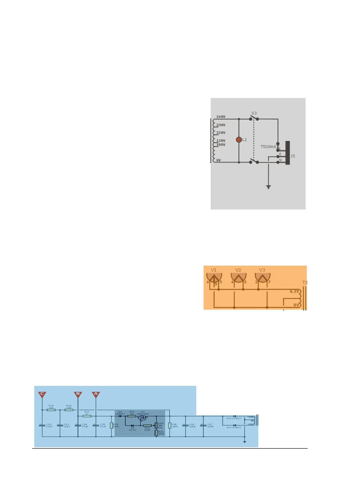
Mains circuit
The signal path runs from left to right at the top of the diagram, but
the power supply runs right to left at the bottom of the diagram. So
the rst stage is the mains circuit, with the IEC mains adapter at
the bottom right.
The light grey section shows the part of the amp that operates
directly from the mains supply. It includes the fuse, On/O switch
and a neon indicator. Just as important is the connection of the
Earth wire from the IEC lead to the amp's metal chassis. Via these
components, the mains is fed to the mains side of the power
transformer, which has a range of inputs to suit your local mains
voltage: 100V, 120V, 220V, 230V and 240V.
Valve heater supply
The mains transformer has two outputs, known as secondary windings. One of these supplies the valves
with a low voltage to (literally) warm them up. This is the heater supply - shown in light orange in this
diagram.
The heater is the part of the valve's internal electrodes that
glows dull-orange when an amplier is switched on. Once it has
warmed up, a valve can start to conduct the guitar signal, but
not before. This is why there's always a small delay between
switching an amplier on and being able to hear any sound.
High-voltage supply
The power transformer also provides a high-voltage AC output in addition to the heater supply. This
high-voltage winding is shown in the light blue section of the block diagram.
It feeds into some diodes which work together to turn the AC voltage into the DC voltage required
by the valves. The large power supply capacitors and resistors lter out mains hum and pass the DC
voltage on to each of the amplication stages (shown by the red triangles).
In the N5X, there's a Variable Voltage Regulator (VCB) circuit - shown here as the darker blue block.
You can use the VCB pot to dial down the voltage supplied to the power stage. There's just one good
reason to do this:
it lets you have
power-valve
distortion at any
room volume,
from 0W and 5W.
 Loading...