vulnerable to excessive heat – if you apply the soldering iron for too long, the heat will transfer to
the plastic which will deform and ruin the switch. The thinner wire absorbs less heat and therefore
requires a shorter soldering time.
4. Solder the two black wires at the Bypass switch FIRST, then mount the switch in the chassis, and
then trim and solder the other ends of these wires at their destinations (lug 3 of the Middle pot and
lug 3 of the Master pot)
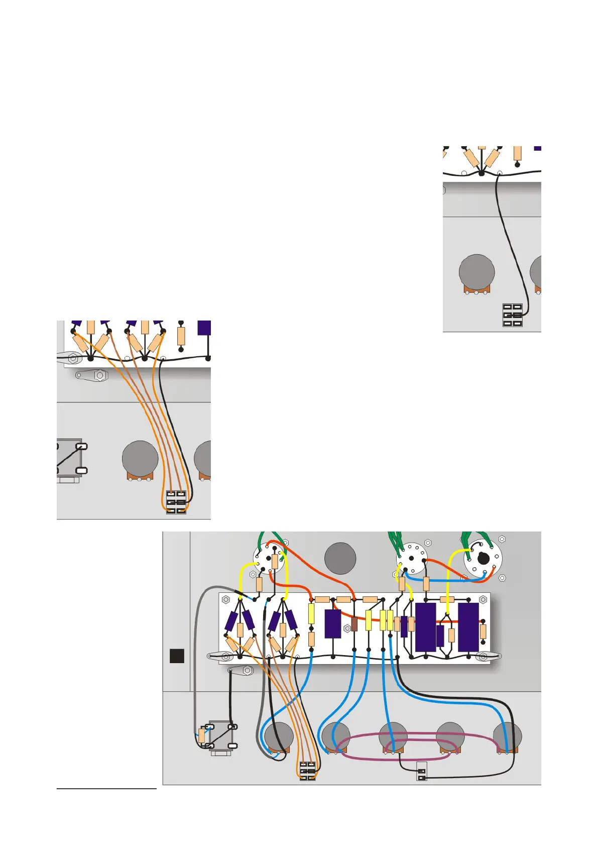
Connecting the Boost switch
The technique you've applied to the Bypass switch is even more important for the
Boost switch (S1), because it has six lugs instead of two! But take the same
approach and it will work out just ne.
Once again, for clarity I have hidden all other wires so that you can
concentrate on the wires and connections we're making here.
First, add a black wire that connects both centre lugs at one end and connects
to the turret shown here (right).
Now add two orange wires and two brown wires to the remaining
four lugs of the switch. If necessary, use a magnifying glass to check
that all wires are separate and there are no shorts from one lug to
another.
Connect the other ends of these four wires to the turrets shown
here. The orange ones connect to the 1uF capacitors and the brown
ones connect to the 47uF capacitors.
30 N5X Construction guide
 Loading...