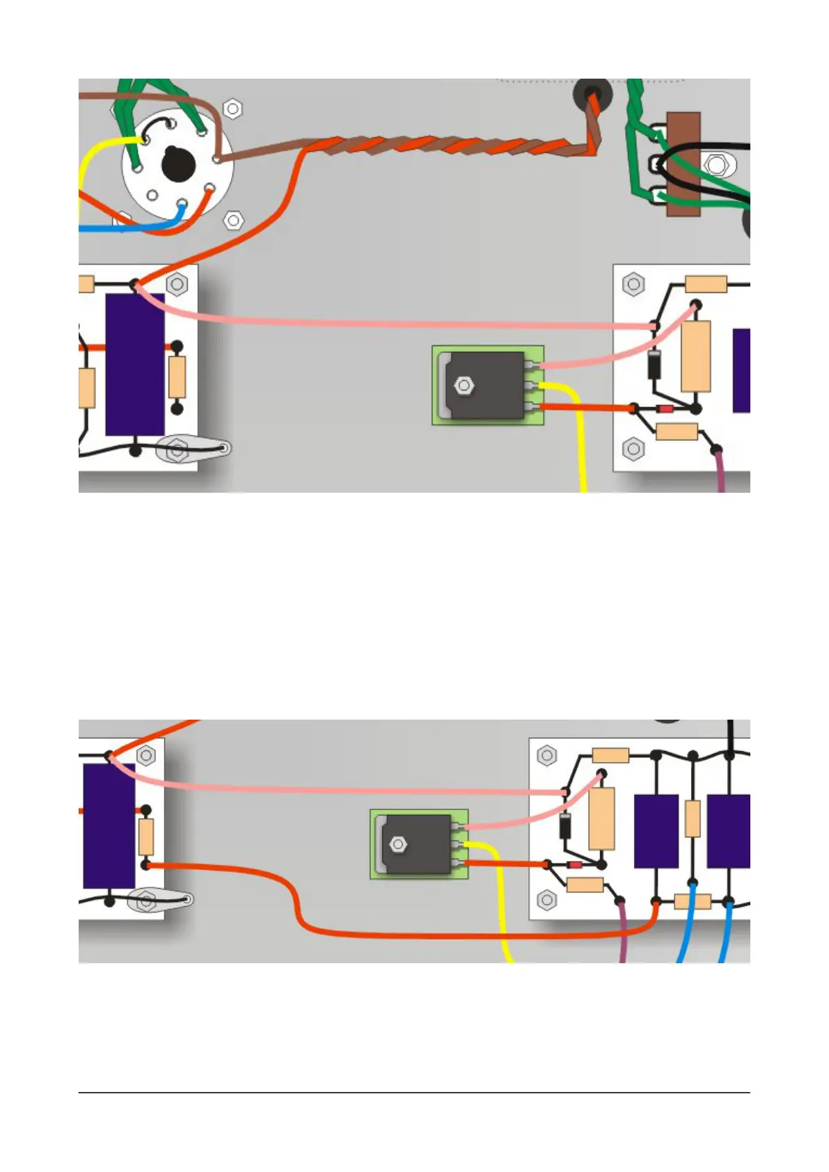
Connecting the turret boards
Take the red wire from the output transformer over to the turret at the top end of C15 - it will connect
here, so trim it to length. But before you solder it, this turret also needs a connection to the output of
our VCB circuit on the other turret board. So take some pink wire and run it from this turret to the
D1+R22 turret on the power supply board.
And nally, there's the preamp's power supply wire to add, also between the two turret boards. Take
some red wire from the as-yet-unconnected turret at the end of R19 on the main turret board and run it
over to the power supply board, to the turret where C13 and R20 meet. Solder this wire and you're all
done building.
Your nished amplier
Now that it's completed, the inside of your N5X chassis should look something like the diagram opposite.
It pays to relax a bit and check o the connections. Look for missing wires, wrong connections and out
of position components.
32 N5X Construction guide
 Loading...