34 N5X Construction guide
Checking the circuit
Previously we've tested the high-voltage power supply and the low-voltage heater supply. Since then
we've added the signal path circuit and connected it to both. Before we power up again, it's worth doing
some basic checks to catch many simple mistakes that could cause the amplier not to work. We'll check
these before applying power to the amplier.
The rst of these are ground continuity checks. Get your amplier chassis on the bench and set all
controls to minimum and set the Boost switch to the centre position and the Bypass switch up. If your
DMM has an audible continuity mode select that, otherwise choose the lowest DC resistance setting. In
these tests, we're looking for a DC resistance of 1 Ohm or so (very few DMMs can accurately display
resistance under 1 Ohm, so you will never get a perfect continuity reading of 0 Ohm).
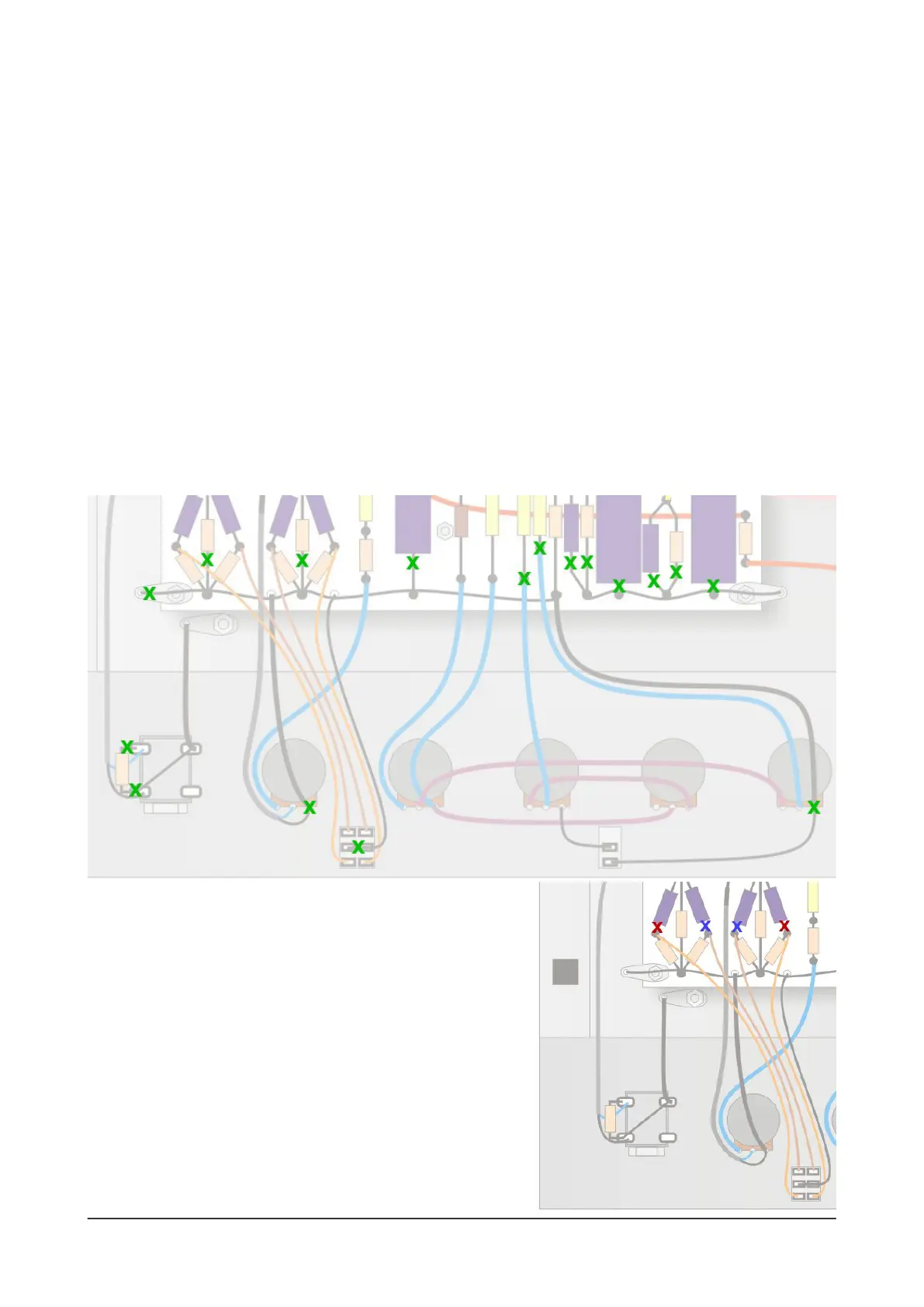
Touch one of the DMM's probes to the chassis grounding lug close to the Input socket (J1) and then
check the points shown in the diagram and check that all of the points with a green X in this diagram
show continuity to ground. If any of them fail this test, check the solder joints and other connections.
Checking the Boost and Bypass switches
The Boost and Bypass switches both alter the grounding of
certain components and connections and you can check
them, too. First, change the Bypass switch and check lug 3
of the Middle pot. It should show no continuity to ground.
The Boost switch has two active positions. Up is the
'Bright' mode and in this position the two points shown with
red 'X' marks should show continuity to ground, but the two
points shown by the blue 'X' marks should not.
Change the switch to the Down position and the amp is
in 'Fat' mode. Now the opposite should be true.
 Loading...