www.SteamPoweredRadio.Com
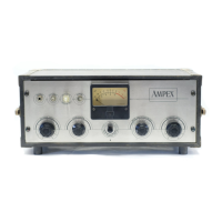
Controls
Tnptt
.l
Tape
Motion
Record Control
Tap
e Speed
Equalization
Reel Size
Record
Inpu
ts
MICROPHONE
BAL
BRIDGE
UNBAL BRIDGE
Reproduce Outpu.t
1-J
cad H
ousin_q
M011itorin.9
( aural and visual)
AH
tape motion is controlled by fom' pu
shb
utton
s, PLAY, STOP,
FAST FORWARD
and
REWIND.
A
separate
RECORD
butt
on on the
fac
e
of
the
electronic assembly,
wh
en pressed, energizes
the
record relay which
dr
ops o
ut
wh
en
the
STOP bu
tton
is
pre
sse
d.
Th
e stereophonic function
(t
wo u·ack)
is controlled
by pressing
the
RECORD
buttons
on
both
elec
tt
onic
ass
emblies
si
mult
aneousl
y.
Tn two track operation, for
cons
istency.
th
e
master
electron
ic
assembly ls usually connected to
the
upp
er
track
in
th
e h
ead
assembly so
that
,
when
the RECORD button
on
the
mast
er ( on I
y)
js
press
ed, recorcling takes
plac
e
on
the
upper track.
T
ape
speed can be changed
by
the TAPE SPEED switch. LOW or
Hl
GH positions
arc
used to
se
le
ct
drive
motor
windings.
An EQUALIZATION switch
on
the face
of
th
e electronic assembly
provides a m
ea
ns
for
se
l
ect
in
g LOW
or
HIGH speed equali
za
tion
appropriate to the tape speed used.
A R
EE
L SfZE toggle switch on the tape
tra
n
sport
makes
possible
se
l
ec
tion
of
the prop
er
tape tension
ing
for
the NAB 1
0½
in
ch
diam
eter
reel
or
the E
IA
5
in
ch and 7 1nch reels.
The INPUT TRANSFER
SW
I
TC
H provides a m
ea
ns for
se
lecting
th
ree different types
of
inputs
:
Input I
mpedancc
150
and
250 oh
ms
n
om
inal
(t
ransformer
can
be strapped
for
30-50 o
hm
s
nomin
a
l.
)
200K
o
hm
s
100K
ohms
Minimum
h
qmt
Signal
that
will produce Operating Level
( 1
~
lllp
e characteri.i:;t'ic
di
stortion)
150
mi
crovolts
-
10
dbm
-10
dbm
Zero indication on the
v-u
meter
corresponds
to
+ 8 dbm ( + 1 db).
Sufficient gain and power h
and
ling
capab
ilities
ex
ist to feed a
+
14
vu
line
outpu
t
into
GOO
ohms
balanc
ed
or
unbalan
ced.
Th
e
center
tap
of
th
e
outp
ut
tr
an
sfor
m
er
can
be strapped to ground
fo
r
balanced
outpu
t. Plus 4 vu also
can
be
obtained by strapping.
(See
IN
STALLATION).
The
e
ras
e, record,
and
re
produ
ce h
ea
ds
are
contained
in
a single
h
ead
housin
g (See SECTION 6
on
HEAD ASSEMBLIES).
Th
e signal on
th
e
tap
e
can
be
monitor
ed while
the
e
quipm
e
nt
is
record
in
g.
Two phone
jacks
are
avail
ab
le to allow monitoring
th
e
r
ec
ord
input
signal, or the o
utput
signal from the reproduce head.
A
sw
it
ch provides a
means
for
makin
g clir
ect
compari
son
between
th
e ori
gina
l program
an
d the recorded program.
Th
e
sa
me switch
transfers
a 4 i
nc
h
vu
meter
for level comparison
and
visual
monitorin
g.
Th
e vu meter also is used to indi
ca
te bias a
nd
erase
curre
nt.
1-3
 Loading...