Magic 485F Adapter Page 5
2.3 Configuration of Magic 485F Adapter Options
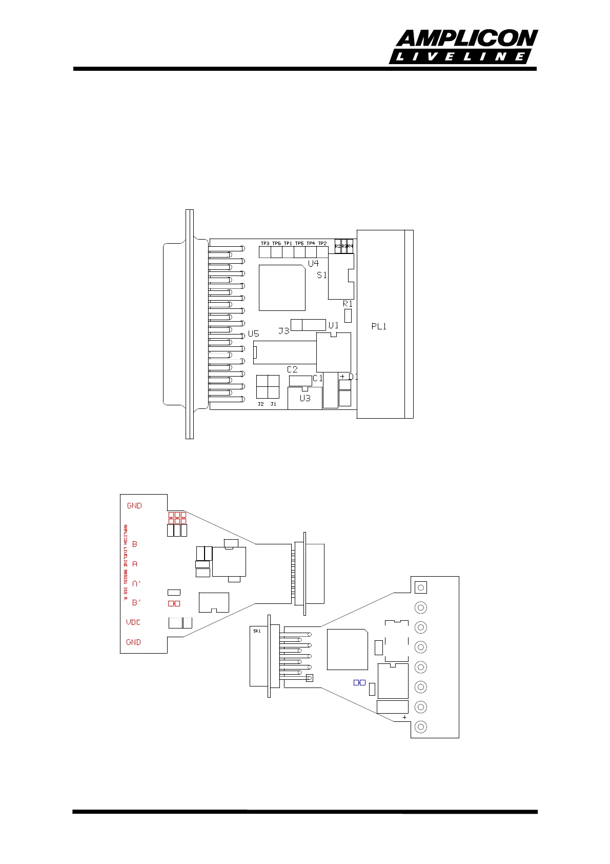
Configuration of the options is undertaken by the setting of links and switches on the baseboard.
For convenience, the plastic case is supplied in two parts and should only be clipped together
when any configuration changes have been made. Operational tests can be performed before
the case is fitted.
FIGURE 2.1 485F25 BOARD LAYOUT AND JUMPER POSITIONS
FIGURE 2.2 485F9 BOARD LAYOUT AND LINK POSITIONS
SK2
C6
R5
C2
C7
R1