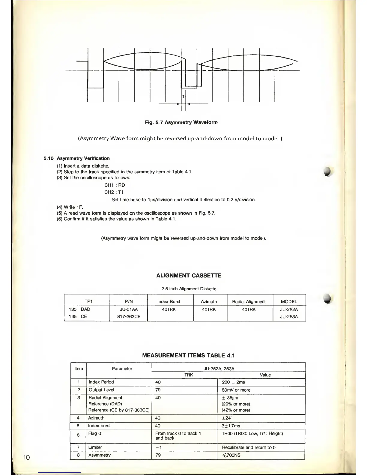
Fig. 5.7
Asymmetry
Waveform
(Asymmetry Wave
form might
be
reversed up-and-down
from model to model
)
5.10 Asymmetry Verification
(1)
Insert a data diskette.
(2)
Step to
the track specified in the symmetry item of Table 4.1.
(3)
Set the oscilloscope
as
follows:
CH1 : RD
CH2 : T1
Set time base to 1
us/division and vertical deflection
to
0.2 v/division.
(4)
Write
1 F.
(5)
A read wave form is displayed on the oscilloscope
as
shown in Fig. 5.7.
(6)
Confirm if it satisfies the value
as
shown in Table 4.1.
(Asymmetry wave form might
be reversed
up-and-down from model
to
model).
ALIGNMENT
CASSETTE
3.5 inch Alignment
Diskette
TP1
P/N Index
Burst Azimuth Radial Alignment MODEL
135 DAD
135 CE
JU-01AA
817-363CE
40TRK
40TRK 40TRK JU-252A
JU-253A
V
MEASUREMENT ITEMS TABLE 4.1
10
Item Parameter
JU-252A, 253A
TRK Value
1 Index Period
40 200
±
2ms
2 Output Level
79 80mV or more
3
Radial Alignment
Reference
(DAD)
Reference
(CE by 817-363CE)
40
±
35(im
(29%
or more)
(42%
or more)
4
Azimuth
40
±24'
5
Index burst
40
3±
1.7ms
6
FlagO From track to track 1
and
back
TROO (TROO: Low, Tr1 : Height)
7 Limiter
-1
Recalibrate
and return to
8
Asymmetry 79
<700NS
 Loading...