w
4. PREVENTIVE MAINTENANCE
No preventive maintenance is necessary for any
type
of FDDs under normal conditions of use.
However if it is determined
that adjustments are necessary, the
following
must be
done.
•
Adjustments (Refer to table
4.1)
(1)
Specify an applicable
model
from Table
4.1, and make a read/write head radial adjustment at a specified track.
(Sides
0,1)
(2)
Make an index timing adjustment
at a
specified track. (Sides
0,1).
(3)
Make an azimuth measurement
at a
specified track (Sides
0,1)
CAUTION
Do not write
when using alignment diskette. Check that write protect sensor is properly operating with
a data
diskette.
Note: Section
9
describes the adjustment procedures in detail.
5. ADJUSTMENTS AND VERIFICATIONS
5.1
Motor
Speed Verification (Index Period)
(1)
Insert
a
diskette, run
the motor, and clamp. Refer to the index period column of Table 4.1 for the applicable model.
(2)
Step to the specified track.
(3)
Connect
a
frequency counter
to
the INDEX signal.
IX (INDEX)
(4)
Check that the frequency
counter
readings
meet the specifications in the table.
5.2 Write Protect Verification
(1)
Check that the exerciser's write protect
lamp goes on and off as
a
media is inserted and removed
as
specified in the
table below.
Media with write protect hole open: ON
Media with write protect hole closed: OFF
5.3 Head Output Verification
Use a new diskette if possible to identify head failure for this check.
(1)
Insert
a good
diskette.
(2)
Run the motor.
(3)
Step to the track specified in the output level column of Table
4.1.
(4)
Connect the oscilloscope probe
as
specified below.
CH1 :
T1
CH2 : T2
EXT : IX (Index)
Invert channel 2 and select the Add
mode.
Set vertical deflection
to 10mV/division and horizontal deflection
to
20ms/division.
(5)
Write 2F
(all ones) on the entire circumference.
(6)
Check that
the average output level meets the specifications of Table 4.
1 .
If it
does not meet the spec-ifications, refer to item
7 of the Trouble Analysis Table.
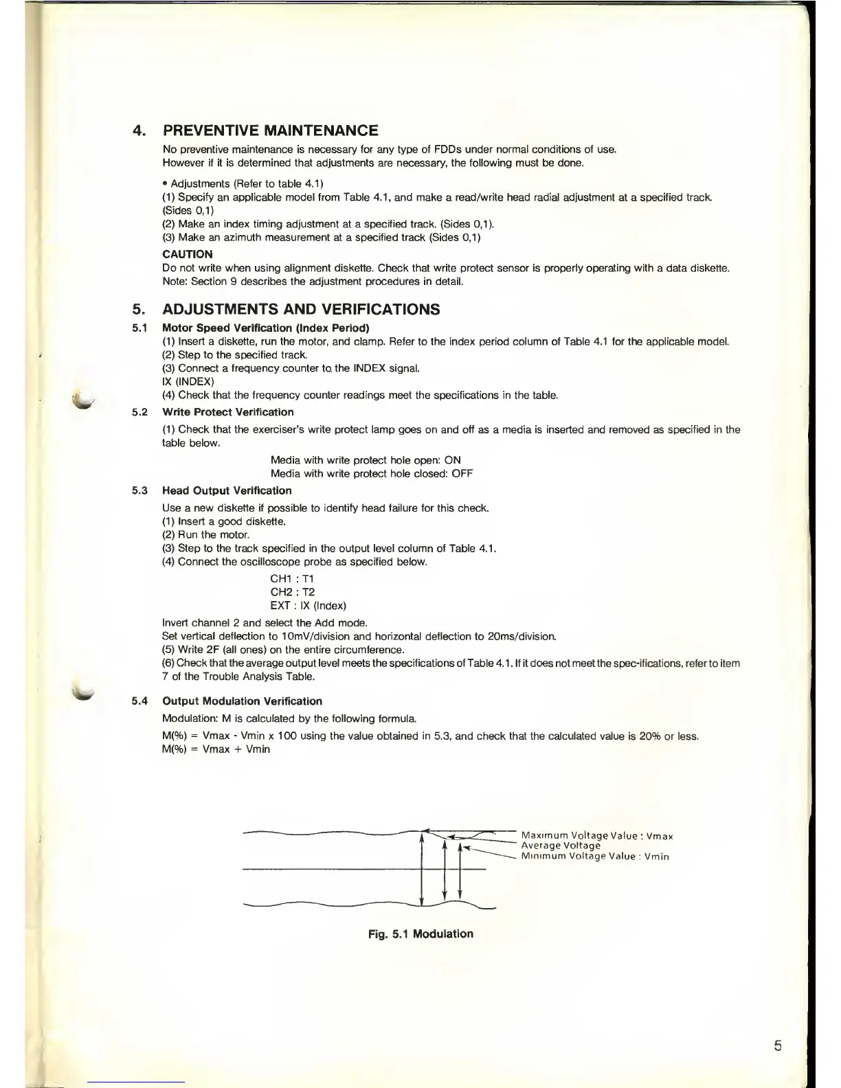
5.4 Output Modulation
Verification
Modulation: M
is calculated
by
the following formula.
M(%)
=
Vmax
-
Vmin
x 100 using the value obtained in
5.3,
and check
that the calculated value is 20% or less.
M(%)
=
Vmax + Vmin
i
'
'
,
]
1
1
'
1
Maximum
Voltage
Value
: Vmax
Average Voltage
Minimum
Voltage
Value
: Vmin
Fig.
5.1
Modulation
 Loading...