5.5
Radial Alignment Adjustment
Introduction
This adjustment
is
normally
not necessary.
If the mounting screws for the
steeper motor loosen, or if
parts become defective, or if
a
compatibility
error occurs, check
and
readjust according
to
the following
procedure.
Steps
(4)
and
(9)
below should
be
performed
regardless of the
type, CE
or
DAD
alignment
diskette
used. Use an alignment dis-
kette suitable to the
type
of FDD
to be adjusted according
to
table.
(1)
Insert an alignment
diskette.
CAUTION:
Be
sure
to leave the alignment diskette
under room conditions for 20 minutes
before adjustment.
(2)
Step to the track specified in the Radial
alignment column of Table 4.1.
(3)
Leave the oscilloscope
in the same condition
as mentioned in section 5.3.
•
Cats Eye System
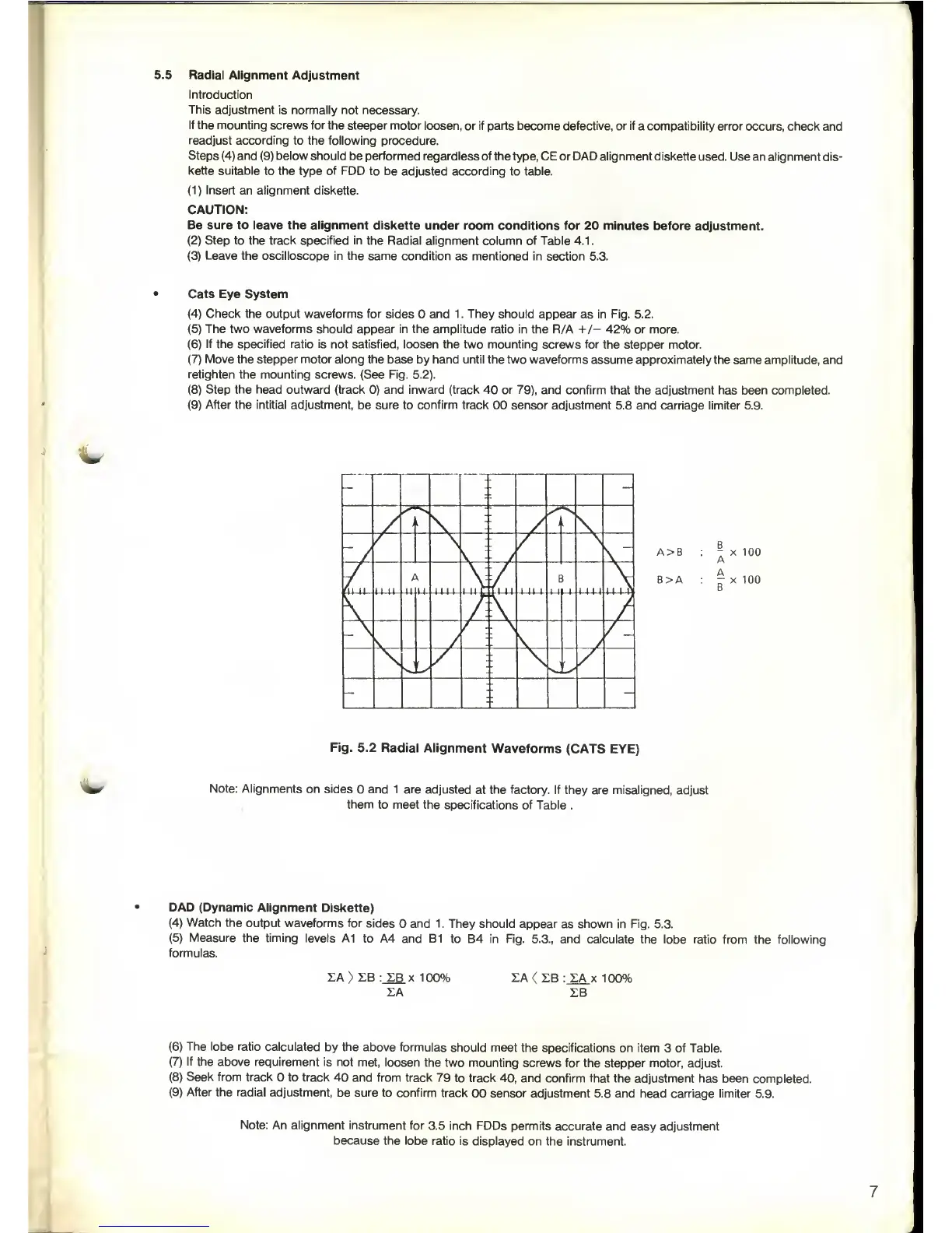
(4)
Check the
output
waveforms
for sides and 1. They should
appear as in Fig. 5.2.
(5)
The two waveforms
should appear in the amplitude ratio in the
R/A
+/-
42% or more.
(6)
If the specified ratio is not satisfied,
loosen the two mounting screws for the stepper
motor.
(7)
Move the stepper motor along the
base by
hand
until the two waveforms assume approximately
the same amplitude, and
retighten the mounting
screws. (See Fig.
5.2).
(8)
Step
the head outward (track
0)
and inward (track 40 or
79),
and confirm
that the adjustment has been completed.
(9)
After the intitial
adjustment, be sure to confirm track
00 sensor adjustment 5.8 and carriage
limiter 5.9.
- -
l
I
/
1
l
-
1
/
s.
-
U-44-
1,
U- III 1
i-W-C li-U- 1
II
1
E
-M
M
i-4-U
-
>
'
-
,1
'
'
- -
A>B
8>A
X 100
X 100
Fig.
5.2 Radial Alignment
Waveforms
(CATS EYE)
Note: Alignments
on sides
and 1 are
adjusted at the factory.
If they are misaligned,
adjust
them
to meet the
specifications of Table .
DAD (Dynamic
Alignment
Diskette)
(4)
Watch
the output
waveforms for sides
and 1. They should
appear
as
shown in Fig.
5.3.
(5)
Measure the timing
levels A1
to A4 and B1
to
B4 in Fig.
5.3.,
and calculate
the lobe ratio from
the following
formulas.
LA
>
SB ZB x 100%
LA
LA
( SB : LA x 100%
SB
(6)
The lobe ratio calculated
by
the
above formulas
should meet the
specifications on item
3
of
Table.
(7)
If the above
requirement is not
met, loosen
the two mounting
screws for the stepper motor,
adjust.
(8)
Seek from track
to track
40
and from
track 79
to track
40,
and confirm that
the adjustment has
been completed.
(9)
After the radial
adjustment, be sure
to confirm track
00 sensor adjustment
5.8 and head carriage limiter 5.9.
Note: An
alignment instrument
for
3.5 inch FDDs permits
accurate and
easy
adjustment
because the lobe ratio
is displayed
on the instrument.
 Loading...