© 2015 Harman. All rights reserved. Alero, AMX, AV FOR AN IT WORLD, HARMAN, and their respective logos are registered trademarks of
HARMAN. Oracle, Java and any other company or brand name referenced may be trademarks/registered trademarks of their respective
companies.
AMX does not assume responsibility for errors or omissions. AMX also reserves the right to alter specifications without prior notice at any time.
The AMX Warranty and Return Policy and related documents can be viewed/downloaded at www.amx.com.
3000 RESEARCH DRIVE, RICHARDSON, TX 75082 AMX.com | 800.222.0193 | 469.624.8000 | +1.469.624.7400 | fax 469.624.7153
AMX (UK) LTD, AMX by HARMAN - Auster Road, Clifton Moor, York, YO30 4GD United Kingdom • +44 1904-343-100 • www.amx.com/eu/
93-1140-08 REV: E
Last Revised: 12/09/2015
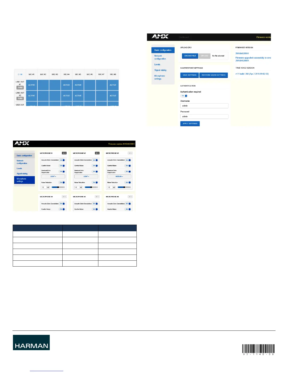
Signal Mixing
This page is provided to configure input to output channel routing and AMM settings.
1. Route analog/digital input channels to each desired output in the signal mixer. By
default almost all input channels are sent to all output channels with these
exceptions; USBin is not routed to USBout, and VCin is not routed to VCout.
Mixing can be set individually for each output channel.
The AMM module will select microphones to open based on activity detected on each
them. Remove any microphones from the selection if they should never be used.
Note: The AMM detects if a microphone is not connected so there is no need to remove
unconnected microphones.
An active microphone(s) is displayed by an "ACTIVE" indicator for that channel as
shown.
2. Disable AMM by pressing the red AMM symbol. This causes all microphone signals
to be added.
Microphone Settings
Use the Microphone Settings page (FIG. 5) to configure the signal processing modules
that operate on the microphone signals.
1. Select 48 VDC phantom power on/off for each microphone.
2. Configure signal processing on each microphone channel as shown in below.
Basic Configuration
Most maintenance tasks like firmware upgrades, store and load settings and change
login credentials are performed in the Basic Configuration page.
Firmware Upgrade
1. Go to the AMX website and download the latest firmware package to the local
drive.
http://www.amx.com/products
2. From the Alero web interface, select the Basic Configuration page.
3. Click Choose File to select the new firmware file from the local computer. The
naming convention of new firmware releases is
firmware-package_yyyymmddhhmm.bin
4. When the new firmware is selected, press Upload to start the firmware upgrade.
Alero will update the firmware and restart. Settings will be stored and used in the
new firmware.
Note: The device will keep its current settings (including network) when upgraded.
Factory Reset
If somehow Alero has ended up in a bad state, there is an option to reset the device to
factory settings. Follow these steps for performing a factory reset.
1. Turn the Alero power OFF.
2. Press the Reset button on the rear panel for approximately 5 seconds while
powering Alero back ON.
3. Wait for Alero to start.
Note: All settings and firmware upgrades will be lost when performing a factory reset
FIG. 4
AMM SETTINGS AND INPUT TO OUTPUT SIGNAL ROUTING
FIG. 5 CONFIGURATION OF SIGNAL PROCESSING APPLIED TO MICROPHONE SIGNALS
SIGNAL PROCESSING OPTIONS DEFAULT SETTING
Acoustic echo cancellation On/off On
Comfort noise generation On/off On
Residual echo suppression On/off On
Residual echo suppression Light/medium/strong Medium
Noise reduction On/off On
Noise reduction 0 dB to TBA dB 12 dB
FIG. 6 BASIC CONFIGURATION PAGE
 Loading...