© 2015 Harman. All rights reserved. Axcess, AMX, AV FOR AN IT WORLD, HARMAN, and their respective logos are registered trademarks of
HARMAN. Oracle, Java and any other company or brand name referenced may be trademarks/registered trademarks of their respective companies.
AMX does not assume responsibility for errors or omissions. AMX also reserves the right to alter specifications without prior notice at any time.
The AMX Warranty and Return Policy and related documents can be viewed/downloaded at www.amx.com.
3000 RESEARCH DRIVE, RICHARDSON, TX 75082 AMX.com | 800.222.0193 | 469.624.8000 | +1.469.624.7400 | fax 469.624.7153
AMX (UK) LTD, AMX by HARMAN - Unit C, Auster Road, Clifton Moor, York, YO30 4GD United Kingdom • +44 1904-343-100 • www.amx.com/eu/
Last Revised: 11/03/2015
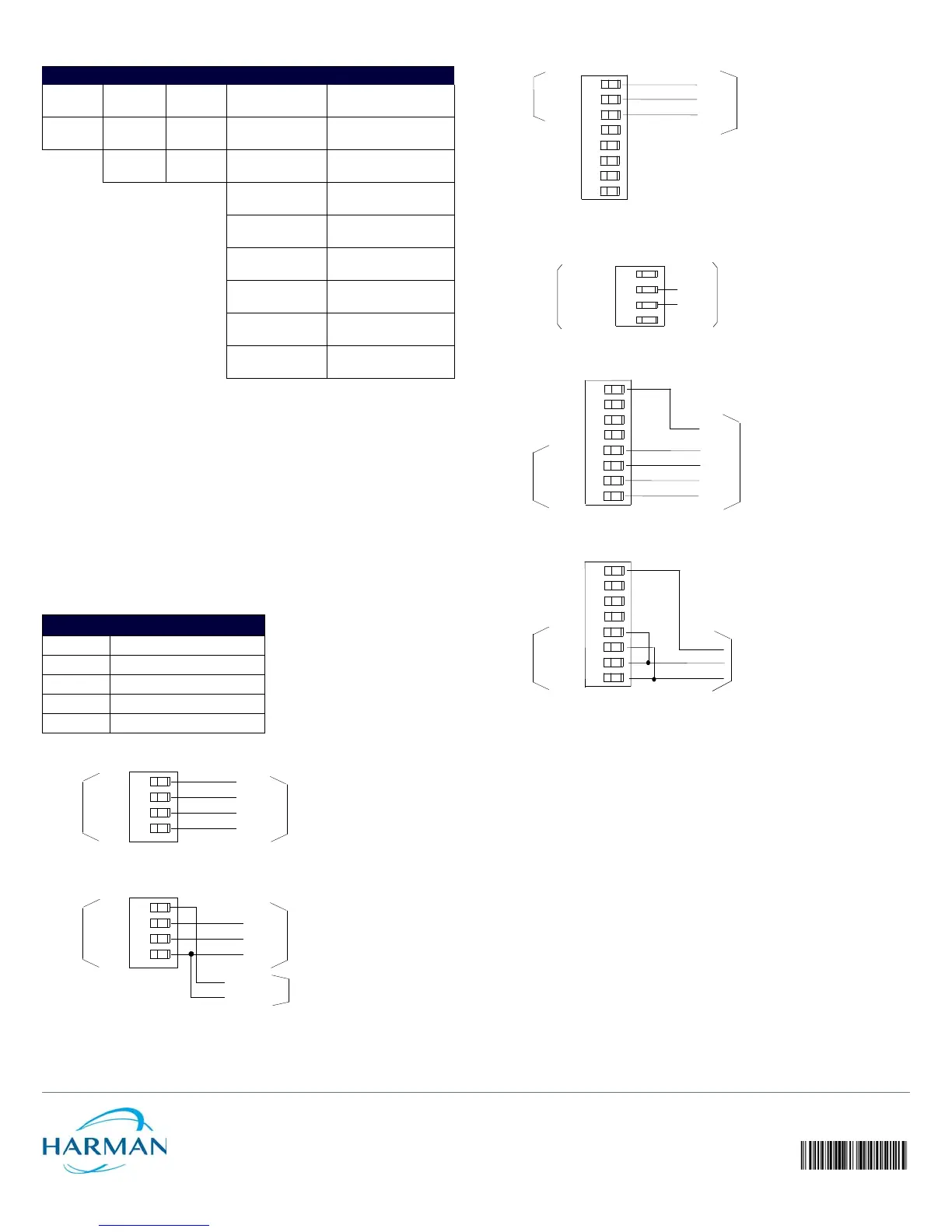
The table below shows the RS-232/422 DIP switch numbers, functions, and their
corresponding values.
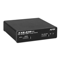
Wiring Devices to the AXB-232++
Preparing Captive Wires
To connect the wiring into a captive-wire connector:
1. Strip 1/4 inch off the wire insulation for all four wires and tin 2/3 of the exposed wire.
2. Insert each wire into the appropriate captive-wire connector up to the insulation.
3. Tighten the captive screws to secure the fit in the connector.
Note: If the device is using a separate power supply, do not connect the power wiring from the
AXB-232++ to that device.
Wiring Guidelines
The interface requires a 12 VDC power to operate properly. The interface uses a PSN2.8 power
supply. The Central Controller supplies power via the AxLink cable or external 12 VDC power
supply.
The maximum wiring distance between the Central Controller and interface is determined by
power consumption, supplied voltage, and the wire gauge used for the cable. The table below
lists wire sizes and maximum lengths allowable between the AXB-RS232++ and Central
Controller. The maximum wiring lengths for using AxLink power are based on a minimum of
13.5 volts available at the Central Controller’s power supply.
Using AxLink
Connect the AxLink wiring to the connector on the AXB-232++ as shown in FIG. 3. i
Using AxLink and External Power Supply
Connect the AxLink and power wiring to the connector on the AXB-232++ as shown in FIG. 4.
Using RS-232
When communicating via RS-232, connect the wiring as shown in FIG. 5.
Using Hardware Handshaking
When the controlled device requires hardware handshaking, connect the wiring as shown in
FIG. 6.
Using RS-422
When communicating via RS-422, connect the wiring as shown in FIG. 7.
Using RS-485
When communicating via RS-485, connect the wiring as shown in FIG. 8.
Rack-mounting the AXB-232++ (optional)
1. Remove any connected power, and AxLink and RS-232 connectors from the rear panel.
2. Remove the 2 screws on the front panel, and remove the front panel and the space
bracket behind the panel.
3. Place the unit in the appropriate opening in the AC-RK.
4. Place the front panel of the AXB-232++ on the front of the rack, over the unit.
5. Fasten the front panel to the rack and unit with the two screws you removed.
Replacing the Lithium Batteries
The AXB-232++’s lithium batteries have a life of approximately 5 years to protect its memory.
When DC power is on, the batteries are not used. When you install the AXB-232++, record the
date the batteries should be replaced.
Note: There is a danger of explosion if you replace the batteries incorrectly. Replace batteries
with the same or equivalent type recommended by the manufacturer. Dispose of the used
batteries according to the manufacturer’s instructions. Never recharge, disassemble, or heat
batteries above 212°F (100°C). Never solder directly to the batteries or expose the contents of
the batteries to water.
Before removing the lithium batteries, contact your dealer and verify that they have a current
copy of your program to avoid an inadvertent loss of data and prevent an unnecessary service
outage.
1. Discharge the static electricity from your body.
2. Unplug the 2-pin power connector and any other connectors.
3. Remove the 2 screws on the front panel, remove the front panel, and slide the circuit
board out of the enclosure.
4. Carefully slide each battery out of its socket, and insert the new battery.
5. Slide the circuit board back into place, replace the front panel and refasten the screws.
6. Reconnect any connectors that you removed.
Additional Documentation
Refer to the AXB-232++ Instruction Manual for programming information.
RS-232/422 DIP SWITCH SETTINGS
Switch 1 2 3 4 5 6 7 8
Function Stop Bits Data Bits Parity Baud Rates
Setting Off Off Off Off Off Off Off Off
Value 2 bits 7 bits Unused 300
On On On Off Off On Off Off
1 bit 8 bits Unused 600
Off On Off Off On Off
Unused 1,200
On On Off On On Off
Unused 2,400
Off Off On Off Off On
Mark 4,800
On Off On On Off On
Even 9,600
Off On On Off On On
Odd 19,200
On On On On On On
None 38,400
WIRING GUIDELINES AT 160 MA
Wire Size Maximum Wiring Length
18 AWG 733.57 feet (223.59 m)
20 AWG 464.11 feet (141.46 m)
22 AWG 289.35 feet (88.19 m)
24 AWG 182.39 feet (55.59 m)
FIG. 3 AXLINK BUS AND +12 VDC POWER WIRING
FIG. 4 AXLINK BUS AND +12 VDC POWER WIRING
PWR
AXP
AXM
GND
AxLink
System
PWR
AXP
AXM
GND
PWR
AXP
AXM
GND
+12 VDC
GND
AxLink
System
Power Supply
PWR
AXP
AXM
GND
FIG. 5 RS-232 WIRING
FIG. 6 HARDWARE HANDSHAKING WIRING
FIG. 7 RS-422 WIRING
FIG. 8 RS-485 WIRING
RTS
CTS
RTS
CTS
1
2
3
4
AXB-232++
Device
Device
TX -
RX +
RX -
AXB-
232++
TX +
TX
RX
GND
+12V
 Loading...