For full warranty information, refer to the AMX Instruction Manual(s) associated with your Product(s).
5/12
©2012 AMX. All rights reserved. AMX and the AMX logo are registered trademarks of AMX.
AMX reserves the right to alter specifications without notice at any time.
3000 RESEARCH DRIVE, RICHARDSON, TX 75082 • 800.222.0193 • fax 469.624.7153 • technical support 800.932.6993 • www.amx.com
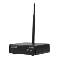
Wiring the AXR-RF
The AXR-RF uses a rear 4-pin AxLink connector for power and data. Power can
be supplied by Central Controller's AxLink cable, or with an optional auxiliary
±12 VDC power supply.
Using the AxLink Connector For Data and Power
Connect the Central Controller's AxLink connector to the AxLink connector
(male) on the rear panel of the AXR-RF for data and ±12 VDC power.
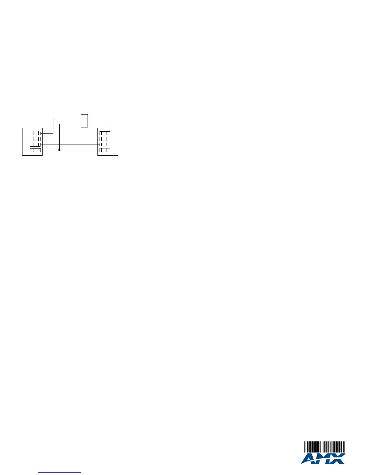
Using the AxLink Connector With an External Power
Supply
Use an auxiliary ±12 VDC power supply when the distance between the Central
Controller and AXR-RF exceeds the limits described in the Wiring Specifications
table.
To use an external power supply, connect the Central Controller's AxLink
connector to the AxLink connector on the rear of the AXR-RF, as shown in
FIG. 3.
Note: Do not connect the wire from the PWR (+) terminal on the Central
Controller to the PWR (+) terminal on the AXR-RF when you connect an
external power supply.
Do not connect power to the AXR-RF until the wiring is complete.
Connect only the GND (-) wire on the AxLink connector when using an auxiliary
±12 VDC power supply. Do not connect the PWR (+) wire to the AxLink
connector's PWR (+) terminal on the Central Controller side of the connector.
Installing the AXR-RF
1. Set the device DIP switch to assign an AxLink device code to the unit.
2. Install the wiring for the AxLink bus.
3. Position the AXR-RF in the location where it will be used.
• Place the receiver close to, or in the middle of, the area to be covered.
• It is recommended that you mount the unit where the antenna is away from
metal obstructions.
4. Extend the antenna vertically for best reception.
If it is necessary to place the antenna in a remote position, use up to 6 ft.
(2 m) of RG-174 coax cable.
5. Connect the AXR-RF to the Central Controller with the AxLink cable.
Note: To avoid potential problems with Axcess processing, do not install two or
more AXR-RF devices, using the same RF frequency, in one system. The AXR-
RF is available in frequencies other than 418 MHz (on request).
6. Locate the green AxLink LED on the front panel and verify that it flashes
once per second. If so, the AXR-RF is communicating properly with the
Central Controller system.
If the LED is on and not flashing, disconnect the AxLink connector and
recheck all AxLink wiring connections. Reconnect the AxLink connector to
the AXR-RF and verify the LED is flashing once per second.
FIG. 3 Auxiliary power supply connection
PWR (+)
GND (-)
+12 VDC power supply (from PSN6.5)
AXR-RF
Central Controller
 Loading...