For full warranty information, refer to www.amx.com
12/07
©2007 AMX. All rights reserved. AMX and the AMX logo are registered trademarks of AMX.
AMX reserves the right to alter specifications without notice at any time.
3000 RESEARCH DRIVE, RICHARDSON, TX 75082 • 800.222.0193 • fax 469.624.7153 • technical support 800.932.6993 • www.amx.com
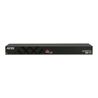
Typical Setup
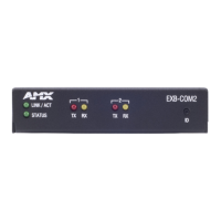
Attaching Input & Output Cables
To attach connectors (1:2 models):
1. Fasten the BNC or RCA connectors from source and destination devices onto
BNC or RCA connectors on module (FIG. 5 shows RCA connectors).
2. Plug the desktop power supply into the power jack on the module and into an
external AC power source.
3. Apply power to the source and destination devices.
4. Adjust DIP switches on front if necessary (FIG. 7 in right column).
Note: The power indicator LED is on the module’s front.
To attach connectors (1:6 models) :
1. Fasten the BNC or RCA connectors from source and destination devices onto
BNC or RCA connectors on module (FIG. 6 shows BNC connectors).
2. Attach the power cord into the power receptacle on the module and into an
external AC power source.
3. Press the “I” side of the power switch.
4. Apply power to the source and destination devices.
Note: The power indicator LED is on the module’s front.
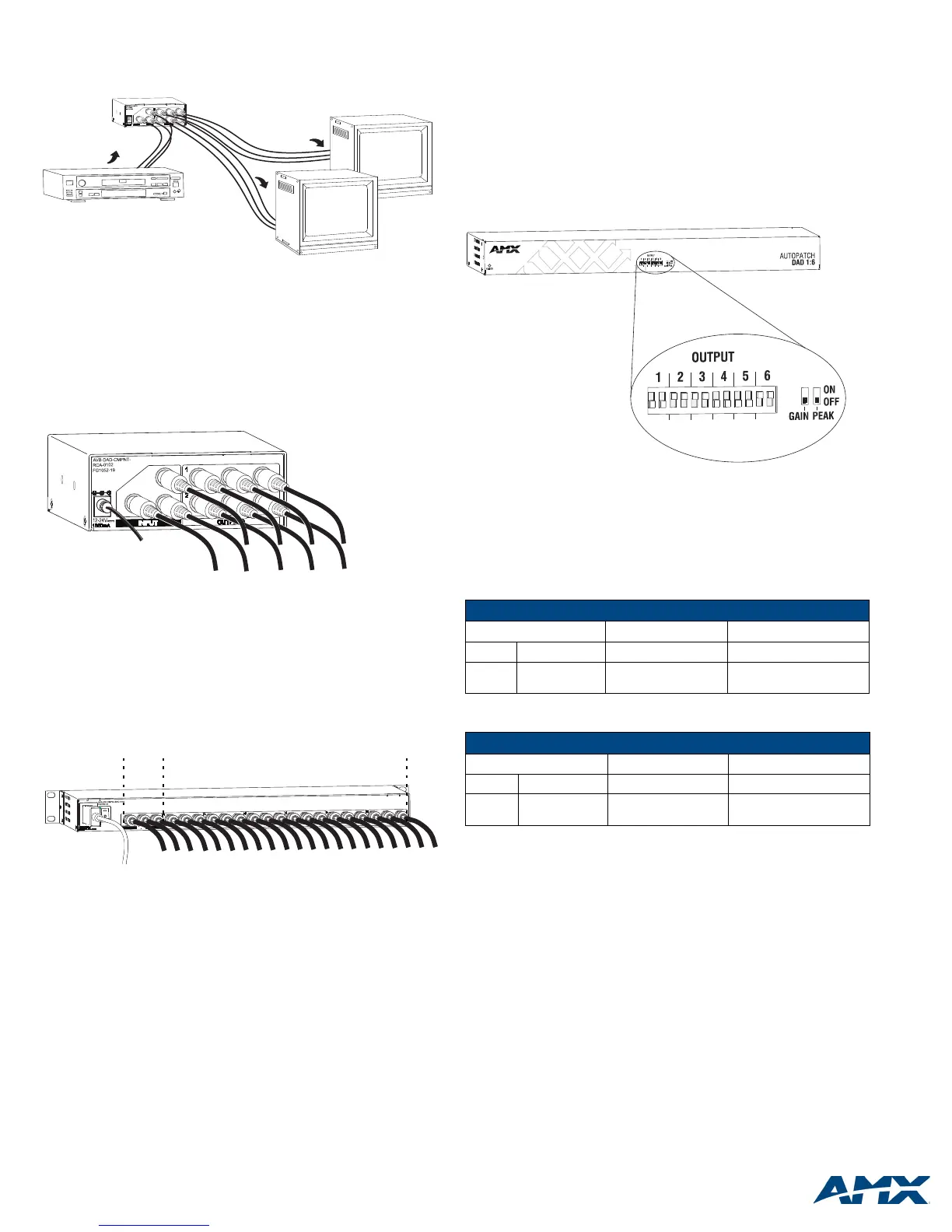
Front Panel DIP Switches
Each DIP switch pair controls the output gain and peak of the same-numbered
output signal. The default setting is both switches “Off” (down, FIG. 7), which
represents unity gain and no peaking. The gain and peak adjustments can
compensate for long cable runs. To increase brightness of a destination’s video, set
the gain DIP switch to “On”. To sharpen a destination’s video, set the peak DIP
switch to “On”.
To adjust DIP switches:
1. Using a small screwdriver or paper clip, flip the toggles on the DIP switches up
(see table below FIG. 7 for settings).
Flip either or both switches “ON” depending on the length of the cable run.
FIG. 4
Typical system setup using 1:2 DA
FIG. 5 Attach input and output connectors (model with RCA connectors shown)
FIG. 6 Attach input and output connectors (model with BNC connectors shown)
Source device
Destination devices
1:2 DAD module
Power
RCAs
From source
To destinations
From
To destinations
Power
BNCs
source
FIG. 7 Adjust DIP switches for gain and peaking
DIP Switch Settings – RGB (BNC)
OFF (default) ON Result
Gain
Unity gain +0.85 dB
Brightens image
Peaking
No peaking
8 dB @ 150 MHz
8 dB @ 300 MHz
Sharpens image
DIP Switch Settings – YPbPr (RCA)
OFF (default) ON Result
Gain
Unity gain +0.85 dB
Brightens image
Peaking
No peaking
9 dB @ 37.5 MHz
9 dB @ 80 MHz
Sharpens image
Example:
Outputs 2, 3, & 6 are set to ON for gain & peaking
Outputs 1, 4 & 5 are set to OFF / unity
 Loading...