Installation of the HPX Base Assembly
The following sections describe the preparation, installation and setup of
the HPX-600/900/1200 Hydraport Base Assembly. A typical installation will
include several various HPX modules.
Note: Refer to www.amx.com for a complete listing of compatible
HydraPort Connection Modules.
Each HPX module has specific instructions for terminating their
connections. Refer to each HPX Module’s Installation Guide during the
installation of the Hydraport system.
Note: Read these instructions in their entirety before beginning the
installation. The installation requires specific steps to be performed
in specific order.
CAUTION: This installation requires specific woodworking skills. This
installation should be performed by an experienced person,
comfortable with these types of woodworking operations. Improper
installation may result in damage to the mounting surface. AMX is not
responsible for damage caused by improper installation.
1) Select a Suitable Location for the HPX Base Assembly
The following figures (FIG. 2 & FIG. 3) indicate the space requirements for
installing the HPX Base Assembly:
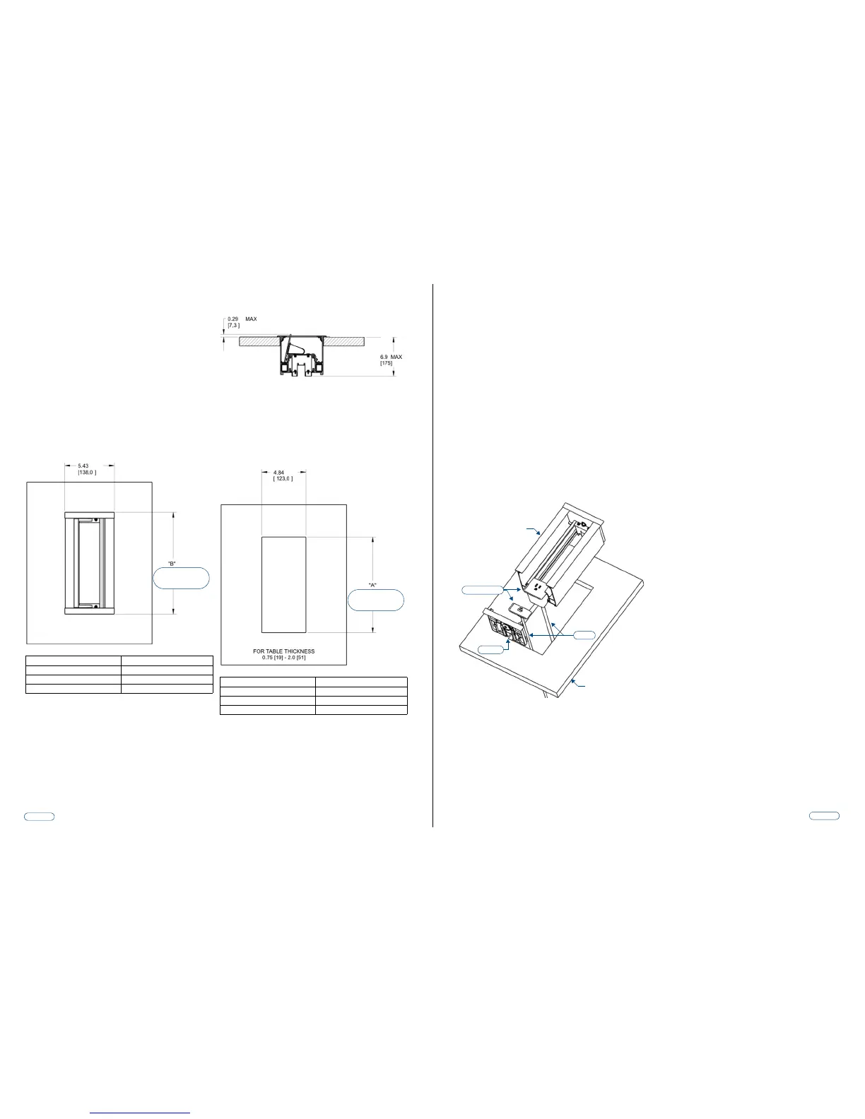
FIG. 3 indicates the dimensions above the table:
• The Hydraport system requires a mounting surface from 0.5” (13mm)
to 2” (51mm) thick.
• The Hydraport system requires at least 6 15/16" (175 mm) below the
mounting surface.
Note: Care should also be taken to ensure that the Hydraport system does
not interfere with the normal use of the work space. For example, on a table
or work surface, ensure that the system does not interfere with the user's
legs when they are seated at the table.
2) Cut the Hole In the Mounting Surface
FIG. 4 provides the Hole cutout dimensions for the HPX Base Assembly:
1. Carefully measure the tabletop or other mounting surface to locate the
desired position of the HPX Base Assembly.
2. Use the cutout template supplied with the HPX Base Assembly to
mark the edges of the cutout.
FIG. 2 Dimensions of the HPX Base Assembly (above the table)
Model Length of “B”
HPX-1200 (Holds up to 12 HPX Modules) 14.09” (358 mm)
HPX-900 (Holds up to 9 HPX Modules) 11.14” (283 mm)
HPX-600 (Holds up to 6 HPX Modules) 8.19” (208 mm)
See table below for the
length of “B” for each
HPX model
FIG. 3 Dimensions of the HPX Base Assembly (below the table)
FIG. 4 HPX Base Assembly - Hole cutout dimensions
Model Length of “A”
HPX-1200 (Holds up to 12 HPX Modules) 13.54 (344 mm)
HPX-900 (Holds up to 9 HPX Modules) 10.59 (269 mm)
HPX-600 (Holds up to 6 HPX Modules) 7.64 (194 mm)
See table below for the
length of “A” for each
HPX model
Note that very little clearance exists between the HPX Base Assembly and
the hole cutout in the mounting surface.
• Take care to align the cutout carefully with the edges or other
appropriate features in the table or mounting surface.
• If the cutout is misaligned, the installed unit will be misaligned.
• Take care to ensure that the top surface of the mounting surface is not
damaged beyond the width of the trim bezel as the cutout is made.
• Use an appropriate drill and drill bit to make a starting hole within the
boundary of the cutout. Use an appropriate saw, such as a jigsaw to
finish the cutout.
• Make sure cutting tool used is appropriate for the material to be cut
and will not tear or chip the top surface.
• Note that the process of making the cutout will create substantial dust
and prepare the environment appropriately.
3) Prepare the Terminations
Some modules that are included in the final system require some type of
backside termination.
Note: Refer to the installation guide for each module to determine the
required backside termination.
• The backside termination for each module can and should be
completed before the module is installed into HPX Base Assembly.
• For terminations for which the far end of the cable is not accessible
(either because the cable has been run under carpet, in a conduit or
structure, or is otherwise fixed), the cable must be placed through the
cutout in the table prior to installation, as indicated in FIG. 5.
4) Insert the HPX Modules
Note the orientation of each HPX Module - a small tab exists on one side of
the faceplate of each module. Ensure all tabs are facing the same direction
(see FIG. 5).
1. Remove one end cap of the HPX Base Assembly by removing the six
sheet metal screws and one pivot screw and pivot pawl assembly.
2. Slide the pre-terminate modules one at a time into the HPX Base
Assembly.
3. Rout the cables from each module out the bottom of the HPX Base
Assembly.
4. Use cable ties and one or more of the sliding clips to secure the
cables as needed to the HPX Base Assembly.
5. Reinstall the end cap of the HPX Base Assembly by installing the six
sheet metal screws and one pivot screw and pivot pawl assembly.
Note: Do not over-tighten the pivot pawl screw (i.e., do not use a high-
powered drill to tighten this screw).
FIG. 5 Inserting the Modules into the Assembly
Interlocking tab
Cables
HPX Base Assembly
Mounting Surface
End Cap
 Loading...