For full warranty information, refer to the AMX Instruction Manual(s) associated with your Product(s).
3/13
©2013 AMX. All rights reserved. AMX and the AMX logo are registered trademarks of AMX.
AMX reserves the right to alter specifications without notice at any time.
3000 RESEARCH DRIVE, RICHARDSON, TX 75082 • 800.222.0193 • fax 469.624.7153 • technical support 800.932.6993 • www.amx.com
WARNING: If using the MXA-MPL’s 2-pin connector for power for a touch panel, please refer
to the MXA-MP/MPL Operation Reference Guide for maximum cable lengths between the
MXA-MPL and the touch panel, based on cable gauge. Using a separate power source for
panoramic panel installations that require long cable runs is highly recommended.
4. When the installation is complete, apply power to the MXA-MPL and to the touch
panel. Verify via the LEDs on the front of the device that it is receiving power and is
connected to the network.
5. If the touch panel has not been configured to receive video signals from the MXA-MPL,
do so now.
FIG. 2 provides a basic installation diagram for the MXA-MP and MXA-MPL:
Note: For PoE-powered Modero X touch panels, the AMX-certified PoE injector must be
connected between the MXA-MPL and the touch panel. Use of a PoE switch in place of an
AMX-certified PoE injector is NOT recommended.
Maximum Power Cable Gauges and Distances
While most Modero X Series touch panels use Power Over Ethernet (PoE) for their power
needs, the panoramic Modero X Series touch panels use external power from an AMX-
certified power source.
The MXA-MPL may be used as a power source for the panoramic touch panels, but only to
certain lengths determined by the cable gauge and the max distance between the device and
the touch panel.
Note: All power cable gauges are in AWG (American Wire Gauge).
When installing panoramic Modero X Series touch panels that exceed these cable lengths
between the MXA-MP/MPL and the touch panel, a separate AMX-certified power source
should be used instead.
Configuring the MXA-MPL
Note: For more information on configuring a Modero X touch panel, please refer to the
Modero X Series Programming Guide, available at www.amx.com. After the MXA-MP is
connected to the network, the touch panel to which it is connected needs to be configured to
receive its signals.
To configure the touch panel:
1. From the Settings page, select Connections & Networks.
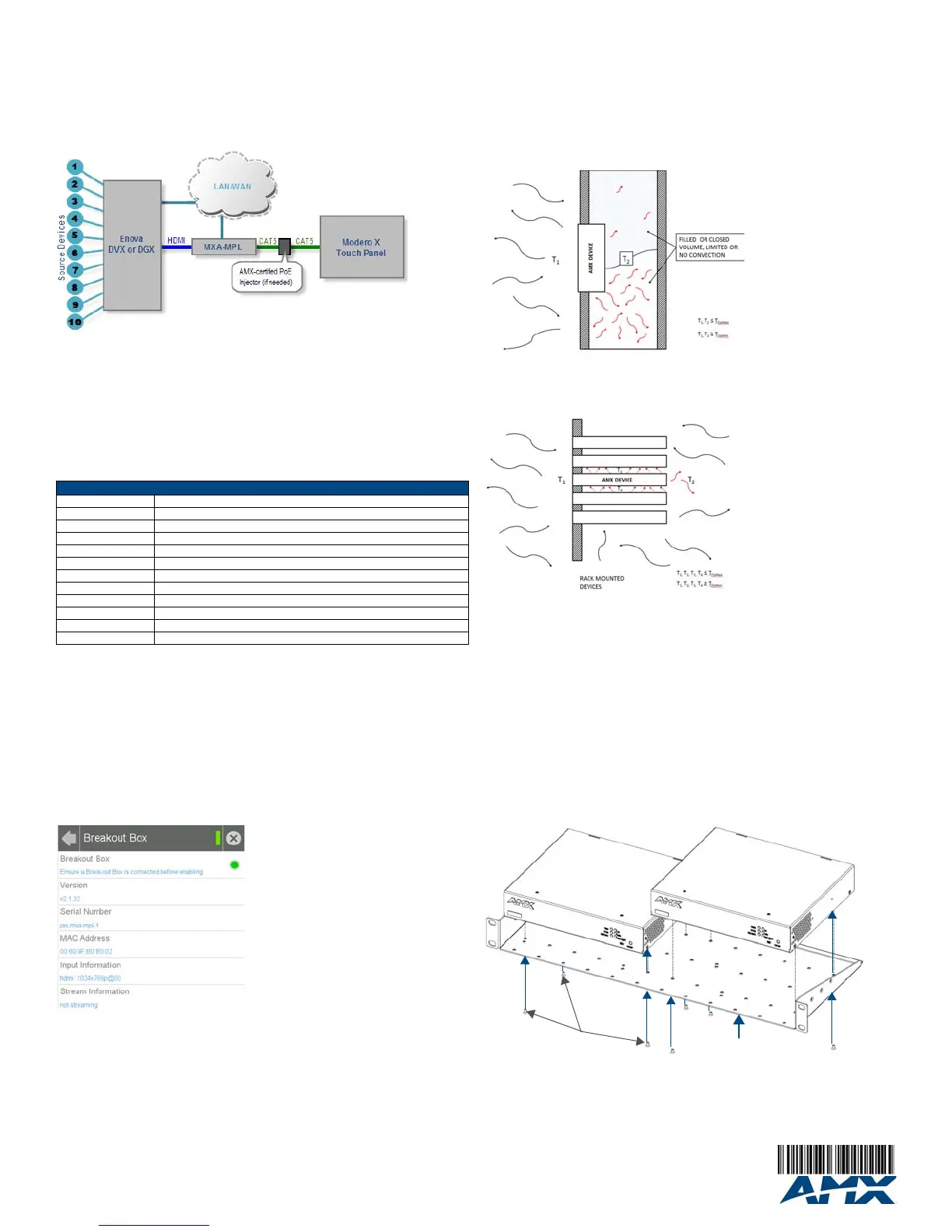
2. From the Connections & Networks page, select Breakout Box to open the Breakout
Box page (FIG. 3).
3. Press the Breakout Box button to enable the panel to receive information from the
MXA-MPL.
4. If the MXA-MPL is connected, the remaining information on the Breakout Box page will
self-populate.
Note: If the MXA-MP is not connected to the touch panel, any attempts at enabling the panel
will fail, and the Breakout Box page will be blank other than the Breakout Box button.
Wall and Rack Installation
Some products are installed in areas of differing temperature and cooling methodologies.
These include products installed in walls, racks, cabinets, etc. Those areas may have
different temperatures and/or cooling approaches that must be taken into consideration to
maintain the product within the specified operating temperature.
FIG. 4 shows an AMX device installed in a wall with a filled volume (such as with insulation or
concrete), as well as with a closed volume (such as between studs in an otherwise finished
wall). The diagram shows how heat generated by the device or other devices may have no
way to escape, and may build up to levels that may affect device operation.
In FIG. 5, the diagram displays an AMX device in a typical rack mounting, with full air
circulation around the front and back of the device. In this case, the main concern is with heat
building up between components, possibly to levels that may affect device operation.
Installation Recommendations
During any installation, a lack of ventilation may produce conditions that may adversely affect
the device’s operation. In these circumstances, special care must be made to make sure that
temperatures within enclosed areas do not exceed the device’s maximum rated temperature.
Note: While the outside temperature of the device may be at or below its maximum operating
temperature, special care must be taken before and during installation to ensure that the
maximum operating temperature is not exceeded within wall or rack installation spaces.
Rack Mounting the MXA-MP
The MXA-MP may be put in a freestanding location, but the device may also be installed in a
standard rack. Installation in a rack requires the use of an (optional) MPA-VRK Rack
Mounting Tray (FG5968-30):
1. Select a position on the Rack Mounting Tray for the installation. The Rack Mounting
Tray contains screw holes to allow single or double MXA-MP installations.
2. Using the screws included with the MPA-VRK, install the screws to the bottom of the
MXA-MP through the Rack Mounting Tray (FIG. 6). Use four screws for each device,
one at each corner.
3. Connect the Rack Mounting Tray to the rack with the provided bolts.
4. Connect the MXA-MP to the network and apply power.
FIG. 2 Installation Diagram - MXA-MP and MXA-MPL
Maximum Power Cable Gauges and Distances
Cable Gauge (AWG) Maximum Distance (feet/meters)
<16 Not recommended
16 24 feet (7.32 meters)
17 20 feet (6.10 meters)
18 15 feet (4.57 meters)
19 12 feet (3.66 meters)
20 10 feet (3.05 meters)
21 8 feet (2.44 meters)
22 6 feet (1.83 meters)
23 5 feet (1.52 meters)
24 4 feet (1.22 meters)
>24 Not recommended
FIG. 3 Breakout Box Settings page
FIG. 4 Heat convection in filled or closed volume, limited or no convection
FIG. 5 Heat convection in rack-mounted devices
FIG. 6 Installing two MXA-MPL devices in a Rack Mounting Tray
 Loading...