For full warranty information, refer to the AMX Instruction Manual(s) associated with your Product(s).
3/14
©2014 AMX. All rights reserved. AMX and the AMX logo are registered trademarks of AMX.
AMX reserves the right to alter specifications without notice at any time.
3000 RESEARCH DRIVE, RICHARDSON, TX 75082 • 800.222.0193 • fax 469.624.7153 • technical support 800.932.6993 • www.amx.com
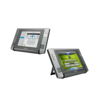
To disconnect and reconnect the MXT-1001’s Ethernet cable to allow use of a hole
smaller than 1.00” in diameter:
1. On a soft surface, turn the MXT-1001 face-down to access the bottom of the
device.
2. Remove the clamp holding the Ethernet cable (FIG. 4) until the Ethernet cable
moves freely.
3. Remove the Ethernet cable connector and pull the cable out of the clamp.
4. Pass the Ethernet cable (ECA5968-05) through the hole, with the RJ45
connector on the other side of the installation surface from the device.
5. Press the Ethernet cable back into the clamp. Do NOT tighten the clamp at this
time.
6. Using a nonconductive item such as a wooden stick, reinsert the Ethernet cable
connector into the device. Use the stick to ensure that the connector is properly
seated.
7. Tighten the clamp to secure the Ethernet cable. Make sure the clamp is around
the bundled black cable, not the individual wires.
8. Connect the RJ45 connector to its incoming Ethernet cable and apply power.
Configuring the MXT-1001
The MXT-1001 is equipped with a Settings app that allow you to set and configure
various features on the panel. For more information on connecting and configuring the
MXT-1001 to a network, please refer to the Modero X Series G5 Programming Guide,
available at www.amx.com.
Accessing the Settings App
To access the Settings app on the MXT-1001, press and hold the Sleep Button
(FIG. 1) on the top of the panel for 3 seconds. The user will be prompted to release the
button to enter the Settings app.
Accessing the NetLinx Subpage
1. From the Settings app page, select NetLinx. This opens a password keypad.
2. Enter the panel password into the keypad (the default is 1988) and select OK to
access the subpage.
Setting the Panel’s Device Number and Device Name
In the NetLinx subpage:
1. Press Device Number to open the NetLinx editing window.
2. Enter a unique Device Number assignment for the panel and press OK.
3. Enter a unique Device Name assignment for the panel and press OK.
Accessing the Ethernet Subpage
1. From the Settings app, select Ethernet. This opens a password keypad.
2. Enter the panel password into the keypad (the default is 1988) and select OK to
access the subpage.
Connecting to a Master
The panel requires that you establish the type of connection you want to make
between it and your Master.
In the NetLinx page:
1. Press Mode to toggle through the available connection modes:
2. If you have enabled password security on your Master, you need to set the user-
name and password within the device.
a. Select Username to open the NetLinx editing window.
b. Set your Username and Master Password.
e. Click OK to return to the NetLinx page.
Configuring the Panel to a Network
The first step is to configure the panel’s communication parameters. This only
configures the panel to communicate with a network, and it is still necessary to tell the
panel with which Master it should be communicating.
Network Communication With a DHCP Address
In the Ethernet subpage:
1. Toggle the DHCP/Static field to open the DHCP/Static window. DHCP is the
default setting.This action causes all fields on the Ethernet subpage (other than
Host Name) to be greyed-out.
2. Select Host Name to open the Host Name window. Enter the new host name
and click OK.
Network Communication with a Static Address
In the Ethernet subpage:
1. Toggle the DHCP/Static field to open the DHCP/Static window.
2. Select Static in the window. This opens the Static IP editing window.
3. Click on any field to open either a keypad (for numeric entries) or keyboard (for
alphanumeric entries). To minimize the keypad/keyboard, click the two down-
ward-pointing arrows at the bottom right corner of the screen.
4. Enter your network’s information in the Static IP editing window. To move from
field to field, simply press the next field you wish to edit.
5. When finished, click OK to save your changes and return to the Ethernet sub-
page.
FIG. 4
Bottom of the MXT-700
Ethernet Cable
Connector
Clamp
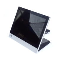
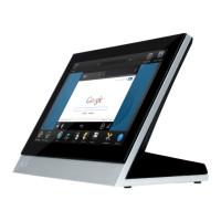
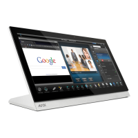
MXT-1001
Connection Modes
Mode Description Procedures
Auto The device connects to the first
master that responds.
This setting requires that you set
the System Number.
Setting the System Number:
1. Select Master System Number to open
the keypad.
2. Set your Master System Number and
select OK.
URL The device connects to the
specific IP of a master via a TCP
connection.
This setting requires that you set
the Master’s IP.
Setting the Master IP:
1. Select the Master IP number to open the
keyboard.
2. Set your Master IP and select OK.
Listen The device “listens” for the
Master to initiate contact.
This setting requires you provide
the master with the device’s IP.
Confirm device IP is on the Master URL list.
You can set the Host Name on the device
and use it to locate the device on the master.
Host Name is particularly useful in the DHCP
scenario where the IP address can change.
 Loading...