For full warranty information, refer to the AMX AutoPatch Instruction Manual(s) associated with your Product(s).
3/07
©2007 AMX. All rights reserved. AMX and the AMX logo are registered trademarks of AMX.
AMX reserves the right to alter specifications without notice at any time.
3000 RESEARCH DRIVE, RICHARDSON, TX 75082 • 800.222.0193 • fax 469.624.7153 • technical support 800.932.6993 • www.amx.com
93-37-861 REV: A0
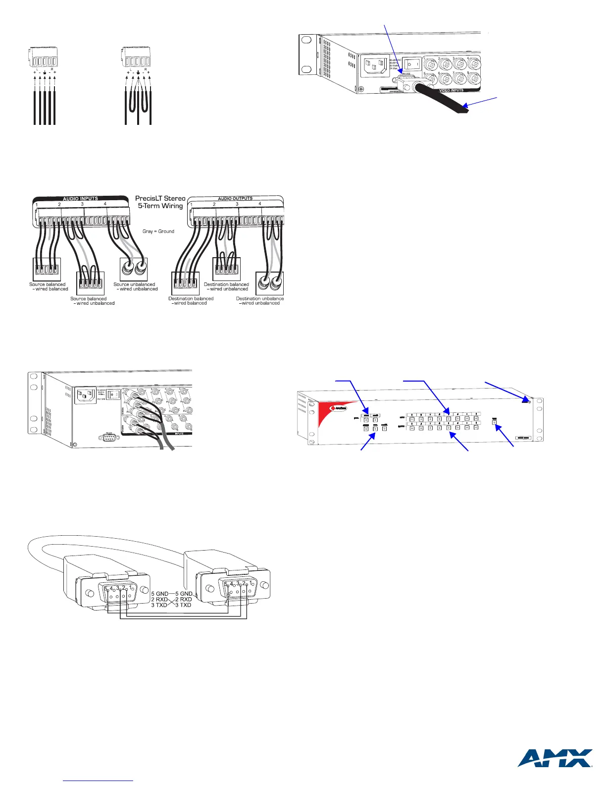
Stereo Audio – 5-Term
Five-position terminal block connectors can be wired for balanced (differential) or
unbalanced (single-ended) stereo audio.
Note: When using a shielded twisted-pair cable, connect the shield (ground) at one
end only (recommend receiving end) to minimize low frequency noise (see FIG. 8).
Source and destination devices require either balanced or unbalanced connections.
More than one of the options shown in FIG. 8 can be used in the same system.
Video & Audio – RCA
RCA connectors are used for component video and unbalanced stereo audio.
The example in FIG. 9 shows RCA jacks attached for routing Y/Pb/Pr and stereo
audio source signals as Input 1.
Establishing Serial Control (if applicable)
The PrecisLT can be controlled by attaching an external control device/system to the
RS-232 serial port.
Serial Control (PCs & third-party controllers)
Use the pinout in FIG. 10 when connecting a PC to the PrecisLT serial port.
To establish external serial control:
1. Plug the null modem cable into the serial port on the enclosure
(see FIG. 11 top of next column).
2. Plug the other end of cable into the serial port on the serial controller/device.
3. Open serial communication software and set port settings to match the
PrecisLT settings (baud = 9600, data bits = 8, stop bit = 1, parity and flow
control = none).
Applying Power & Control Startup
Important: We recommend attaching all power cords to a surge protector and/or
an AC line conditioner.
To apply power:
1. Attach power cord(s) and plug into power source (turn on power source if
necessary). Press the “l” side of the enclosure’s power switch. The Power
Indicator on the front of the enclosure illuminates.
2. Apply power to any external devices (PCs, SBCs, etc.) and then to the source
and destination devices.
Completing the Installation
We recommend completing the installation by executing a test switch routing Input 1
to Output 2. The PrecisLT ships with a default switch routing Input 1 to all outputs.
This default switch must be disconnected before performing a test switch. The
method of executing the switch depends on the control option used (see below).
• Front Control Panel – press Cancel Key to ensure panel is in Switch Mode.
To disconnect the default switch: Press Input Key 1. Input Key 1 blinks and all
output keys illuminate. Press each output key, then press the Take Key. When
all the output keys turn off, the default switch is disconnected.
To execute a test switch: Press Input Key 1. Input Key 1 blinks. Press Output
Key 2. Output Key 2 illuminates. Press the Take Key. When the illuminated
keys turn off, the switch is successful.
• NetLinx
®
or Duet Compatible Devices – see the specific controller device
documentation for instructions on installation and executing switches.
• APControl 3.0 (PC based) – install and open the program. From the
APControl Launchbar menu, select System/New; select Heritage System/Next;
select Manual Configuration Entry/Next; enter and Add VM information/Next;
finish Wizard instructions. From the Launchbar menu, select Views/CrossBar
and click on the crosspoint for Input 1 / Output 2.
• APWeb – connect the APWeb Module (see the APWeb Module Quick Start
Guide). For instructions on executing switches, see the APWeb (Interface)
supplement on the AMX AutoPatch CD.
• BCS Commands (HyperTerminal) – when power is applied, a short splash
screen appears.
To disconnect the default switch: enter DI1T into the terminal
emulation program.
To execute a test switch: Enter CI1O2T (routes Input 1 to Output 2). When
CI1O2T appears, the switch is successful.
The system is now ready to attach the remaining source and destination devices.
Additional Information Covered in PrecisLT Instruction Manual
See the instruction manual on the CD or at www.amx.com for the following:
• Control panel operations
• BCS commands for system operation
• Product specifications for specific models
FIG. 7
Balanced audio Unbalanced audio
FIG. 8 Options for source-to-PrecisLT-to-destination 5-Term wiring
FIG. 9 Insert the RCA plugs into the RCA jacks
FIG. 10 RS-232 null modem cable pin diagram
FIG. 11 Connect the null modem cable to the serial port
FIG. 12 Typical PrecisLT control panel
Serial port
Null modem
serial cable
Take Key
Level Keys
Input Keys
Command Keys Output Keys
Power Indicator
 Loading...


