CALL (978) 977-3000
Fast, Easy Operation
With the 2030, generating precision waveforms is easier
than ever. From simple menus, you can readily select
either standard functions and modulations, or a host of
functions from a built-in library. Frequency and other
parameters are instantly set with a single, large control
knob that gives the instrument a real-time “analog feel.”
Specific values are keyed-in directly. More than 50 com-
plete waveform setups can be stored internally by name,
for immediate output when needed.
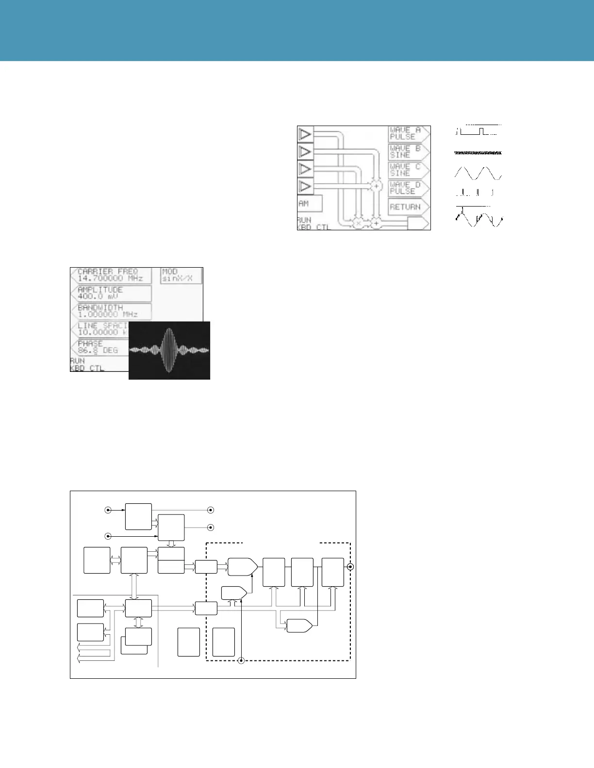
Producing even complex, custom waveforms is no prob-
lem with the graphic display and soft keys. An interactive
flow diagram enables the user to sum and modulate differ-
ent standard functions as desired. In the example
shown, Wave A (top input of diagram) modulates Carrier
C; then B and D are added. Desired noise levels may be
added before or after modulation. In fact, an endless vari-
ety of signal combinations are at the operator’s fingertips.
Precision and Versatility
Because of its enormous flexibility in waveform genera-
tion and its excellent signal quality, the 2030 Waveform
Synthesizer is virtually immune to obsolescence.
In production test, for example, where changes and
upgrades to manufactured product often call for expensive
new test equipment, the 2030 will be a viable signal
source through many years of product change. Should
new types of modulation or more accurate signals be
required, the synthesizer is ready.
The synthesizer’s floating analog
output to ensures immunity to noise
problems encountered in system test
set ups. It also offers triggered start,
stop, or windowing, and generates
counted waveform bursts that either
stop at the end of a complete cycle or
stop and hold the current level. A
high-stability frequency reference is
standard. Multiple-unit synchroniza-
tion is provided through common
clocking or by locking frequencies
with an external reference.
Exact bandwidth of the sinx/x
modulated burst is menu-selectable.
Flow diagram represents modulator, carrier and waveforms
added to obtain the output shown.
× C
A
+ B
+ D
=
Non-Vol RAM
DSP
IEEE-488
Vernier
DAC
Offset
DAC
RS232
Trigger Input
Sync
Output
Output
Selector
50Ω /600Ω
or Open
Super Linear
DAC
Filter:
20 MHz,
1 MHz,
100 kHz
Ext. Reference
or
Sample Clock
High Speed
Timing &
Memory
Controller
Ext. AM
Input
10 MHz
Output
Waveform RAM
12 Bit
High
Accuracy
Reference
Oscillator
Precision
0–66 dB
Atten.
Calculation
Section
Output
Section
12 Bit
Supertwist
LCD
Display
Control
Software
ROM & RAM
Keypad &
Rotary
Control
Analog
Control
Bus
Isolation
Circuit
Isolation
Circuit
RAM for
DSP Math
Routines
Main
Power
Supply
Floating
Power
Supply
Shielded Floating Output Section
Control
Processor
The Model 2030 Block Diagram.