13
Step 13: Select the appropriate belts for your chassis configuration, and loop one belt over each Pulley on each
Center Wheel Assembly.
Step 9: Slide two 5/16” washers (am-1009) onto each CIM
motor shaft against the round boss of the motor. Place
the Machine Key (am-1121) into the keyway of the motor
shaft. Slide the 14 tooth (am-0034) gear onto the shaft up
to the washers, while aligning the keyway of the gear to
the key. Use a 7/16” socket to press the 8mm Retaining
Clip (am-0033) onto the face of the gear, with the tabs of
the clip pointing toward the motor shaft.
Line up the CIM motors with the mounting
holes in each Toughbox Mini. Secure each motor with
gears installed to the Toughbox Mini housing using
two 10-32 x 0.625” SHCS w/ Nylon Patch (am-1120).
The long chassis requires 160
tooth belts (am-2266).
The wide chassis requires 120
tooth belts (am-2704).
The square chassis requires
131 tooth belts (am-2571).
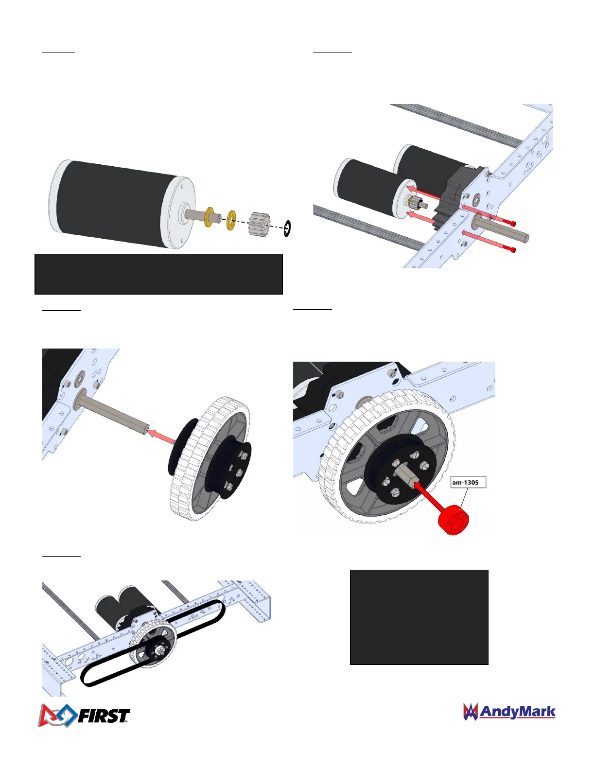
Step 12: Place the Hex Spacer (am-1305) onto each
Toughbox Mini Hex Output Shaft and press into the round
cavity in the pulley. The shaft will help align the spacer
hex bore with the wheel hub hex bore.
Step 11: Place a Center Wheel Assembly onto each
Toughbox Hex Output Shaft with the aluminum
hub facing towards the Inside Plate.
NOTE: Each drive gearbox can accept up to 2
motors. Repeat this step for each motor.
 Loading...