Copyright by Servizio Clienti ANGELO PO Spa
35
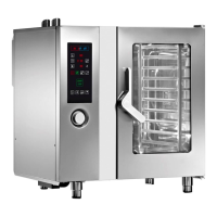
CPU board (1a) included the display and keys with LED backlighting. It is connected to the
keyboard (1b) with two flat cables and to the power card (2) with a network cable (RJ45).
The power board (2) receives all the signals from the oven probes (PT1000 temperature
sensors, door micro switch, core probe, etc.) and controls all organs of the oven through
the appropriate relays. Communicates with the CPU card (1a), with the inverter (4) and the
combustion and fan control boards (3) (for gas model only) via RJ45 network cables.
If there is no communication between the power board and the CPU board or the
combustion control board the alarm E13 appears (communication failed error).
Transformer PCB
2 outputs 12Vac to the PCB 2
and from this to the CPU 1a
5

 Loading...