2-2 Spectrum Analyzer Function Verification Performance Verification 1
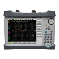
2-10 PN: 10580-00177 Rev. D MS2721B MM
Procedure:
1. Set the MG3692x Synthesized Signal Generator to 50.1 MHz CW and set the output level to –30 dBm.
2. Connect the synthesized signal generator output to the Spectrum Analyzer RF In connector of the
MS2721B through the 50 MHz lowpass filter, as shown in Figure 2-4).
3. Set the MS2721B to Spectrum Analyzer mode and then preset the instrument.
4. Set the MS2721B as follows:
Center Frequency: 50.1 MHz
Span: 100 kHz
Reference Level: –20 dBm
Attenuation Level: 0 dB
RBW: 1 kHz
VBW: 10 Hz
Detection: Peak
5. Press the Shift key and then the Trace (5) key. Press Trace A Operations and set # of Averages to 5.
6. After the Trace Count displays "5/5" (left side of display), press the Marker key and press Peak Search.
7. Record the amplitude of the 50.1 MHz signal in the test record, Table A-4, “Spectrum Analyzer Second
Harmonic Distortion” on page A-3.
8. Change the Center Frequency of the MS2721B to 100.2 MHz. Do not adjust the MG3692x Synthesized
Signal Generator.
9. After the Trace Count shows "5/5", press the Marker key and press Peak Search.
10. Record the amplitude of the signal at 100.2 MHz in Table A-4.
11. Convert the values of the 50.1 MHz and 100.2 MHz signals to positive values and subtract the smaller
from the larger. Record the result in Table A-4, and verify that it is within specification.

 Loading...


