SECTION VI
UL EX-4510 12-1-01 Page 6-9
Installation
INSTALLING DISTRIBUTION PIPING (Continued)
Distribution Manifold And Piping
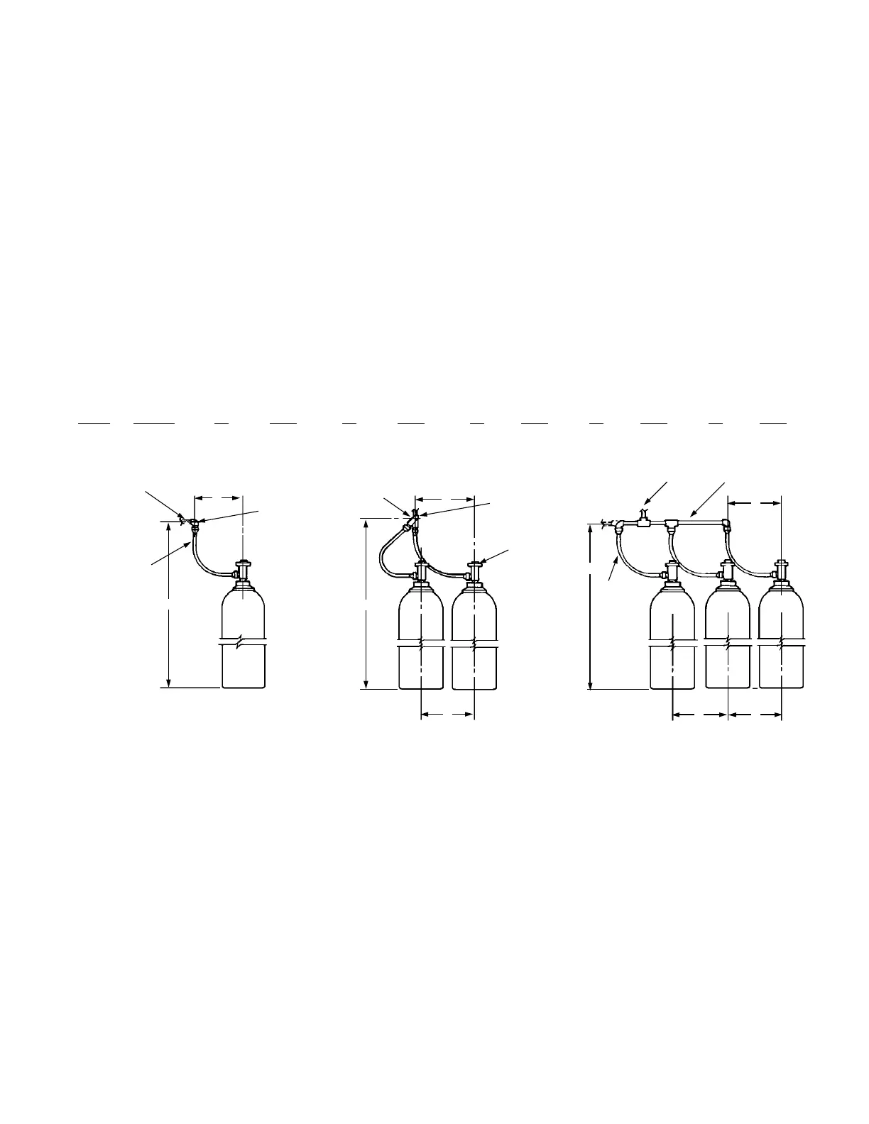
1. Starting with the cylinder manifold, securely mount the
manifold at the appropriate height as shown in Figure
8. Make certain that if accessories piping is to be done
later that the end of the manifold contains a tee
instead of an elbow. The outlet of the tee will later be
reduced down to 1/4 in. for piping to the accessories.
1 Cylinder 2 Cylinders 3 Cylinders
Manifold Height and Spacings
Cylinder Size Dimension A Dimension B Dimension C Dimension D Dimension E
cu. ft. (cu. m) in. (cm) in. (cm) in. (cm) in. (cm) in. (cm)
570 (16.1) 79 (201) 79 1/2 (202) 12 (31) 12 (31) 12 (31)
A
A
B
C
D
C
E E
E
SUPPLY PIPE
SUPPLY PIPE
1/2 IN. ELBOW
“Y” FITTING
INERGEN
VALVE
FLEXIBLE
DISCHARGE
BEND,
PA RT NO.
427082
FLEXIBLE
DISCHARGE
BEND,
PA RT NO.
427082
SUPPLY PIPE HEADER
FIGURE 8
002209