S19 Maintenance Guide
2
7. When powering on the hashboard, user must first connect the negative copper wire of the power supply, then the positive copper wire of
the power supply, and finally plug in the signal cable. When removing, the order of installation must be reversed. First remove the signal
cable, then remove the positive copper wire of the power supply, and finally remove the negative copper wire of the power supply. If the
user do not follow this order, it is very easy to cause damage to R8, R9, U1, U2 (not all chips can be found). Before testing the pattern, the
repaired hashboard must be cooled down before testing, otherwise it may cause PNG testing.
8. To replace a new chip, printing pins and soldering paste are required to ensure that the chip is pre-soldered and then soldered to the
PCBA for repair
III. Hashboard tester making and matters needing attention
The supporting fixture of the hashboard tester should satisfy the heat dissipation of the hashboard and facilitate the measurement of signals
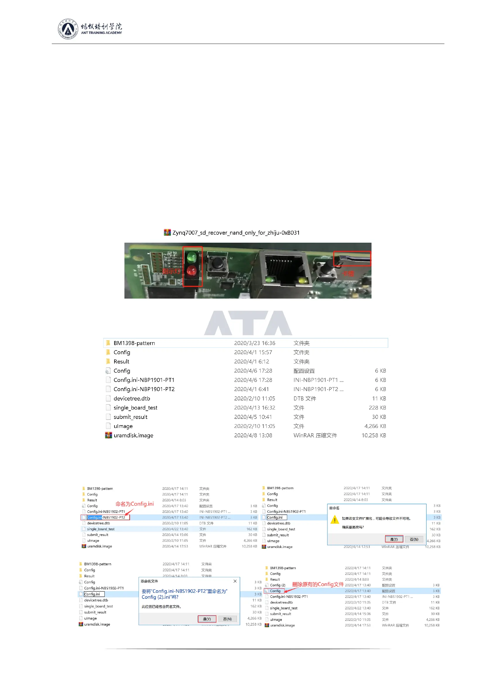
1. Use the 19 series hashboard tester SD card swiping program for the first time to update the hashboard tester control board FPGA, unzip
it and copy it to the SD card, and then insert the card into the hashboard tester card slot; power on for about 1 minute and wait for the
control board indicator to double flash 3 times, then the update is completed; (if it is not updated, it may cause a certain chip to be bad
during the test)
Figure 3-1
2. Make the test SD card according to the requirements, and directly unzip the compressed package of the single-sided heat sink inspection
chip to make the SD card;
Figure 3-2
3. The test SD card will be made according to the requirements, and the double-sided heat sink 8-times Patter test needs to make an SD
card, as shown in the figure below;
Figure 3-3 Figure 3-4
Figure 3-5 Figure 3-6
 Loading...