APW9 Power Supply Maintenance Guide
5
● Distribution on the front panel of the power supply: two triangle-shape AC input
interface
three size-4028 high speed fans
●Distribution on the left side of the power supply: four PCB-33 copper soldering
terminals with adjustable voltage output
one 4Pin signal terminal
one 12V fixed voltage output PCIE terminal
●Distribution on the rear panel of the power supply: cooling vent,it forms the outlet of
the high-speed fan.
●The model of the AC input terminal on the power supply front panel is C14, and the AC
input cable of the C13 interface is required.
●The 4Pin signal terminal is the interface between the external control panel and the
power supply. The SDA/SCL is the I2C protocol, and can adjust the output voltage of the
power supply through I2C. EN is the enable signal of the power supply, and the control
panel can enable the power supply through EN, which is effective in low level.
●The output part of the adjustable voltage adopts four PCB-33 copper soldering terminals,
90-degree side foot binding posts, M4 high current horizontal fixed seat; the 2 terminals
close to the air outlet are output positive poles, and 2 near signal terminals are output
negative poles, the output line or output copper bar can be fixed on terminal by M4 screw,
which is convenient and flexible to use.
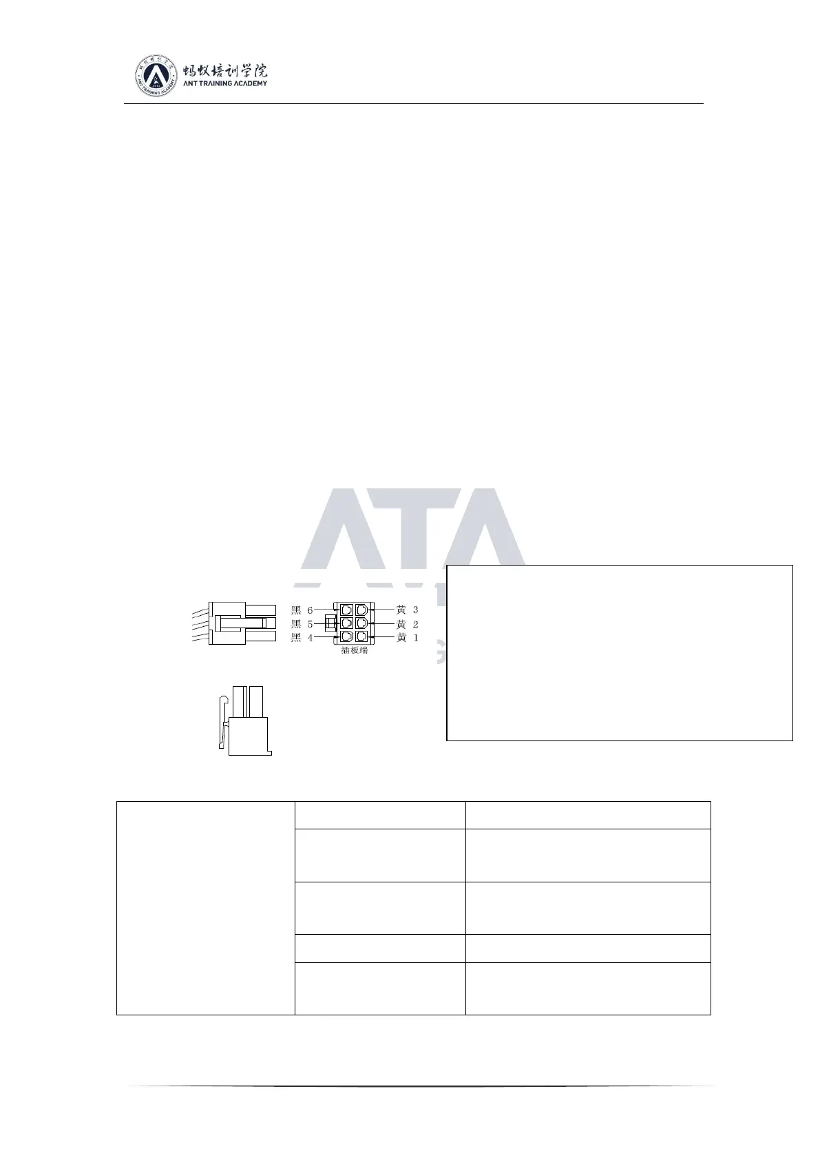
●The output part of the 12V fixed voltage uses the PCIE output terminal. The PCIE
output terminal diagram is as follows:
1.4 Parameters of APW9 Power Supply:
The PCIE output line consists of two color
lines, the 12V positive line is yellow, and the
negative line is black.
Definition of 6PIN PCIE terminal positive
and negative poles:
Positive pole: yellow 1, yellow 2, yellow 3
Negative pole: black 4, black 5, black 6
 Loading...