Anybus X-gateway Gateway Installation Sheet
www.anybus.comSP1747, rev. 2.10, Oct 2015
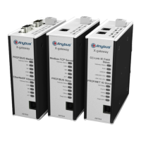
Front view
GW Status
GW Status
USB Connector (X4)
2–4 interface-specific LED Indicators
(see Network Installation Sheet)
Gateway Status LED
Gateway Status LED
2–4 interface-specific LED Indicators
(see Network Installation Sheet)
Top-mounted interface
Bottom-mounted interface
Concept
The Anybus X-gateway acts as a translation device between two
different fi eldbus networks.
Network 1
Network 2
24 VDC
USB
Internally the gateway consists of two separate network interfaces,
mounted at the top and bottom end of the gateway respectively, and a
translation device handling communication between the interfaces.
For more information about the specifi c interfaces, please refer to the
Network Installation Sheet for each fi eldbus network.
Top view
Power Connector (X3)
See Network Installation Sheet
for connector details
Bottom view
See Network Installation Sheet
for connector details
DIN Rail Mounting (standard)
Align the gateway with the DIN rail connector, then press fi rmly on the
top end and push the lower end into place.
To dismount the gateway, press fi rmly on the top end, then pull the
lower end away from the DIN rail.
1
2
Mount
1
2
Dismount
DIN Rail Mounting (sideways)
Remove the sticker covering the screw holes on the right side panel.
Unscrew the DIN clip from the back and refi t it to the side panel.
Mount/dismount the gateway the same way as in standard mounting.
Remove for optional DIN retting
Screw holes behind sticker
T10
Technical Support
Technical support, documentation and software downloads are
available at www.anybus.com.
Power Connector (X3)
Pin Signal
+ 24 VDC ±20 % Class 2
– Ground
Gateway Status LED
Indication Meaning
Green Communication running
Red Communication error
Red (fl ashing) Network interface error
The interface-specifi c LED indicators are described in the Network
Installation Sheets for the respective fi eldbus network interfaces.
Technical Specifi cations
Power supply 24 VDC ±20 % Class 2
Power consumption 200 mA at 24 VDC (typical)
400 mA at 24 VDC (maximum)
Operating temperature -25 to +65 °C @ 400 mA/24 VDC
Non-operating temperature -40 to +85 °C
Relative humidity 5–95 % non-condensing
Protective Earth (PE) Internal connection to PE via the DIN rail