I/O data
5-2
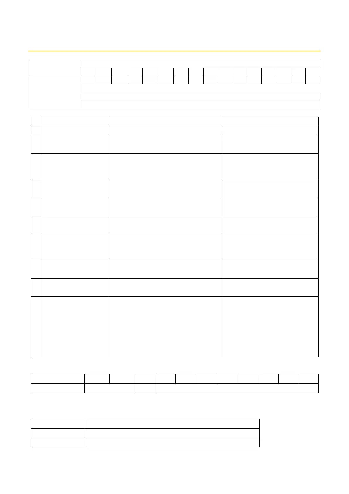
5.1.2. Status inputs
Number of connected units
Latest error occurrence ID
DP/DN short circuit
error
Upon detection of a short circuit on
DP or DN on the ASLINK system
Error flag clear (M) OFF ON
24 V power supply
low voltage error
Upon detection of low voltage on the
24V DC power supply for the ASLINK
system
Error flag clear (M) OFF ON
DP-DN disconnection
error
Upon detection of DP-DN
disconnection
Error flag clear (M) OFF ON
Upon detection of an error for which
an alarm is issued
Error flag clear (M) OFF ON
Slave unit access
error flag
Upon detection of an error in a slave
unit’s response in the parameter area
Error flag clear (M) OFF ON
Parameter write in
progress flag
Parameter write command (P) OFF
ON
If the parameter write command
(P) was OFF after a parameter
write operation
Automatic address
recognition flag
During the process of automatic
address recognition
Automatic address recognition
not in operation
Slave unit
replacement flag
During execution of the single unit
simplified replacement function
At completion of the single unit
simplified replacement function
At shift to the adjustment mode
* When the small display unit
(optional) is connected, setting the
unit in the adjustment mode
activates the adjustment mode.
At reset of the adjustment mode
* When the small display unit is
disconnected, or when the
small display unit is changed
from the adjustment mode to
the normal mode, the
adjustment mode is reset.
The ID format is as shown below.
I/O type: “00” means an output slave unit
“01” means an input or input/output mixed unit
Output slave unit address 0–254
Input or input/output mixed slave unit address 0–254
E.g.) Input slave unit address #30 = ID 0x21E
Output slave unit address #60 = ID 0x03C
 Loading...