990-4618A-001 InRow™ Chilled Water Air Conditioners Technical Specifications 19
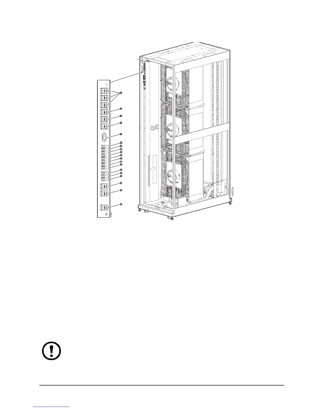
User interface connection—ACRC500/ACRP500 series
Note: For a top installation, control wiring is routed through the wire channel located at the top left
hand corner just above the user interface connectors.
Note: For a bottom installation, the control wiring is routed to the access hole in the bottom of the
equipment through wire clamps from the interface connectors. Then, the wiring is routed down
along the electrical panel and secured with wire clamps.
Rack inlet temperature sensors 1, 2, 3
Supply 24 V DC (current limit: 20 mA)
A-Link IN
Customer input + (12–30 V AC/V DC, 24 V DC @ 11 mA)
A-Link OUT
Customer input - (12–30 V AC/V DC, 24 V DC @ 11 mA)
Network port
Modbus D1
Console port
Modbus D0
Customer output, NC (Normally Closed)
Modbus GND
Customer output, COM (Common)
Supply air temperature sensor (front)
Customer output, NO (Normally Open)
Supply air humidity sensor (front) (ACRP500 series only)
Supply GND (Ground)
Display interface
Supply 12 V DC (current limit: 20 mA)
 Loading...