9
XL4 2nd Stage Maintenance Manual
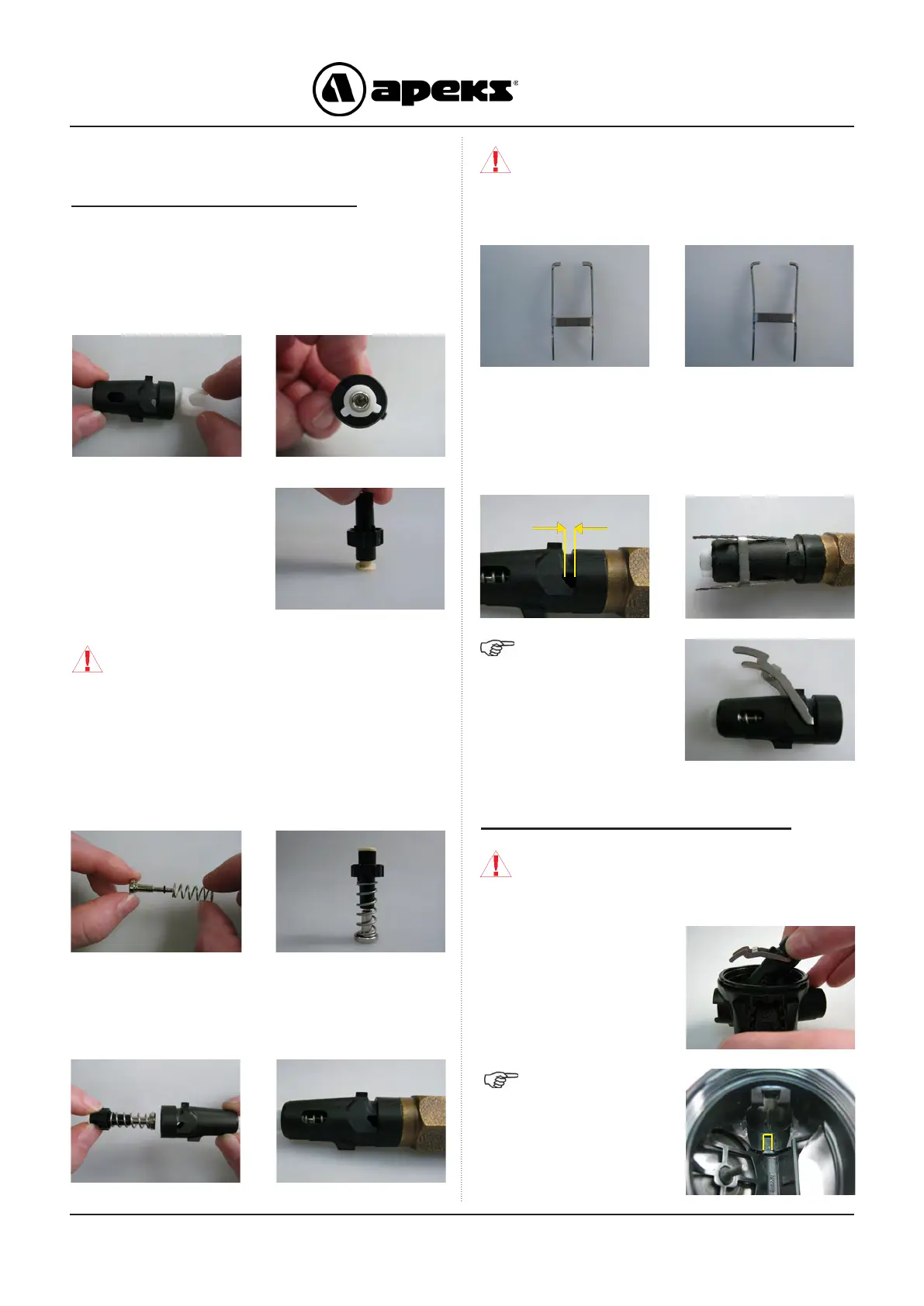
REASSEMBLY PROCEDURES
Assembling of the Spindle Body
CAUTION: Ensure that the Lever is not
twisted and that legs are parallel. Lever
should appear as that shown on the left, not
as shown on the right. If necessary, gently
squeeze legs together to straighten.
NOTE: Ensure that
the Lever has a full
range of movement
and does not catch
on the Valve Spindle
Body. Ensure that the
spring can be seen
through the Valve
Spindle Hole.
1. Carefully insert the Spindle Adjuster Sleeve (22) into
the Spindle Body (14). Ensure that two legs of the Spindle
Adjuster Sleeve correctly line up with the slots in the Body.
Check the Spindle Adjuster Sleeve is rmly pressed into the
end of the Body.
3. Install a new lubricated ‘O’ ring (25) onto the Spring
Carrier (23), followed by the Spring (24). Fit the Shuttle
Valve (26) onto the Spring Carrier and Spring, carefully
guiding the end of the Carrier into the bore of the Shuttle
valve.
2. Press the Shuttle Valve
(26) down rmly onto the
Silicone Valve Seat (27),
making sure it is fully
engaged.
CAUTION: Ensure the work surface is clean
and free from debris. DO NOT mark the face
of the Silicone seating, this will cause the 2nd
stage to leak when fully assembled.
4. Insert the Spring Carrier end of the assembly into the
Spindle Body (14). Screw in the AT48 tool to fully compress
the Spring until it passes the triangular shaped hole in the
Body.
5. Insert the feet of the Lever (15) into the gap, this retains
the Shuttle Valve inside the Body. Ensure the feet are
engaged fully in the Shuttle Valve (26) and the Lever is
parallel to the Spindle Body (14). Press down on the Lever
(15) to disengage the Silicone Seat (27) and remove the tool
AT48.
GAP
Fitting Spindle Assembly into Case
CAUTION: DO NOT use the lever to push
the Spindle into the case as this will bend the
lever.
6. Insert the Spindle Body
assembly into the Case.
Insert the Spindle Adjuster
side rst into the Venturi
Lever hole then slide back
so the Silicone Valve Seat
end engages into the Body
snug.
NOTE: The longer
lug on the underside
of the Spindle Body
(14) should engage
into the slot in the
Body (13).

 Loading...