Technical Data
Operating Voltage 18–28V DC
Maximum Loop Current Consumption at 24V
Switch-on Surge 1.2mA for <1 sec
Quiescent 330µA
Sounder Operated 4mA Max
Sounder Beacon Operated: 92/100dB(A) 9mA Max
Sound Output 100dB(A)
IP Rating - Type A 21C
IP Rating - Type B IP33C (IP66C**)
** Non EN 54 certi ed
For sound pressure levels measured to EN54–3 see document PP2203 and for isolator operation informa-
tion see document PP2090, both available on request.
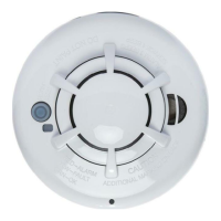
IP Rating
To maintain the integrity of the enclosure it is essential that suitable IP rated cable glands be used.
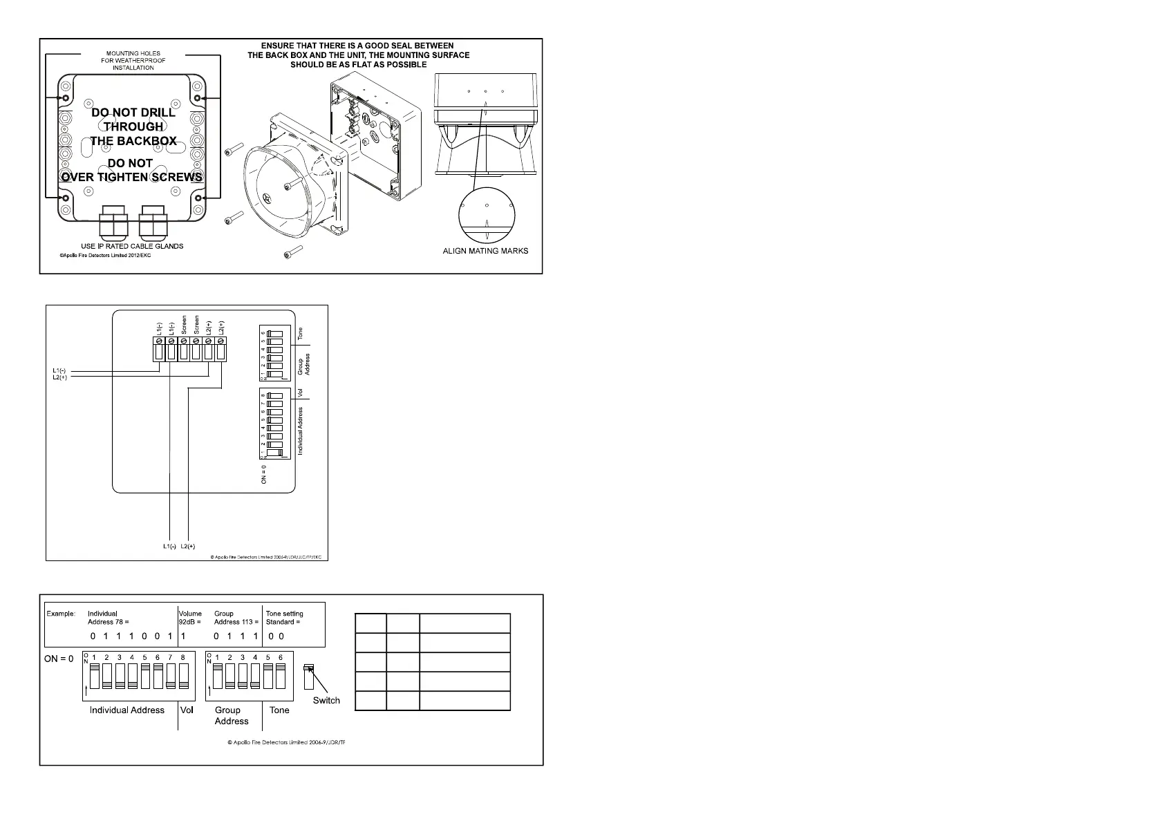
Individual Address Setting
The address of the Multi-tone Open-area Alarm Devices is set using seven segments of the eight-seg-
ment DIL switch. The eighth seg ment is used to adjust the volume output. Segments 1-7 of the switch are
set to “0” (ON) or “1”, using a small screwdriver or similar tool. A complete list of address settings is shown
below.
DIL switch DIL switch DIL switch DIL switch DIL switch
setting setting setting setting setting
addr 1234567 addr 1234567 addr 1234567 addr 1234567 addr 1234567
1 1000000 11 1101000 21 1010100 31 1111100 41 1001010
2 0100000 12 0011000 22 0110100 32 0000010 42 0101010
3 1100000 13 1011000 23 1110100 33 1000010 43 1101010
4 0010000 14 0111000 24 0001100 34 0100010 44 0011010
5 1010000 15 1111000 25 1001100 35 1100010 45 1011010
6 0110000 16 0000100 26 0101100 36 0010010 46 0111010
7 1110000 17 1000100 27 1101100 37 1010010 47 1111010
8 0001000 18 0100100 28 0011100 38 0110010 48 0000110
9 1001000 19 1100100 29 1011100 39 1110010 49 1000110
10 0101000 20 0010100 30 0111100 40 0001010 50 0100110
51 1100110 61 1011110 71 1110001 81 1000101 91 1101101
52 0010110 62 0111110 72 0001001 82 0100101 92 0011101
53 1010110 63 1111110 73 1001001 83 1100101 93 1011101
54 0110110 64 0000001 74 0101001 84 0010101 94 0111101
55 1110110 65 1000001 75 1101001 85 1010101 95 1111101
56 0001110 66 0100001 76 0011001 86 0110101 96 0000011
57 1001110 67 1100001 77 1011001 87 1110101 97 1000011
58 0101110 68 0010001 78 0111001 88 0001101 98 0100011
59 1101110 69 1010001 79 1111001 89 1001101 99 1100011
60 0011110 70 0110001 80 0000101 90 0101101 100 0010011
101 1010011 106 0101011 111 1111011 116 0010111 121 1001111
102 0110011 107 1101011 112 0000111 117 1010111 122 0101111
103 1110011 108 0011011 113 1000111 118 0110111 123 1101111
104 0001011 109 1011011 114 0100111 119 1110111 124 0011111
105 1001011 110 0111011 115 1100111 120 0001111 125 1011111
126 0111111
Fig 3. Example of address and tone setting
Tone Setting
5 6 Tone
0 0 Standard
1 0 Slow Whoop
0 1 DIN
1 1 Standard
The alert or evacuate mode is selected
using the appropriate settings on the
CIE (Control & Indicating Equipment
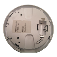
Fig 2. Wiring
Fig 1. Mounting Type B weatherproof products

 Loading...