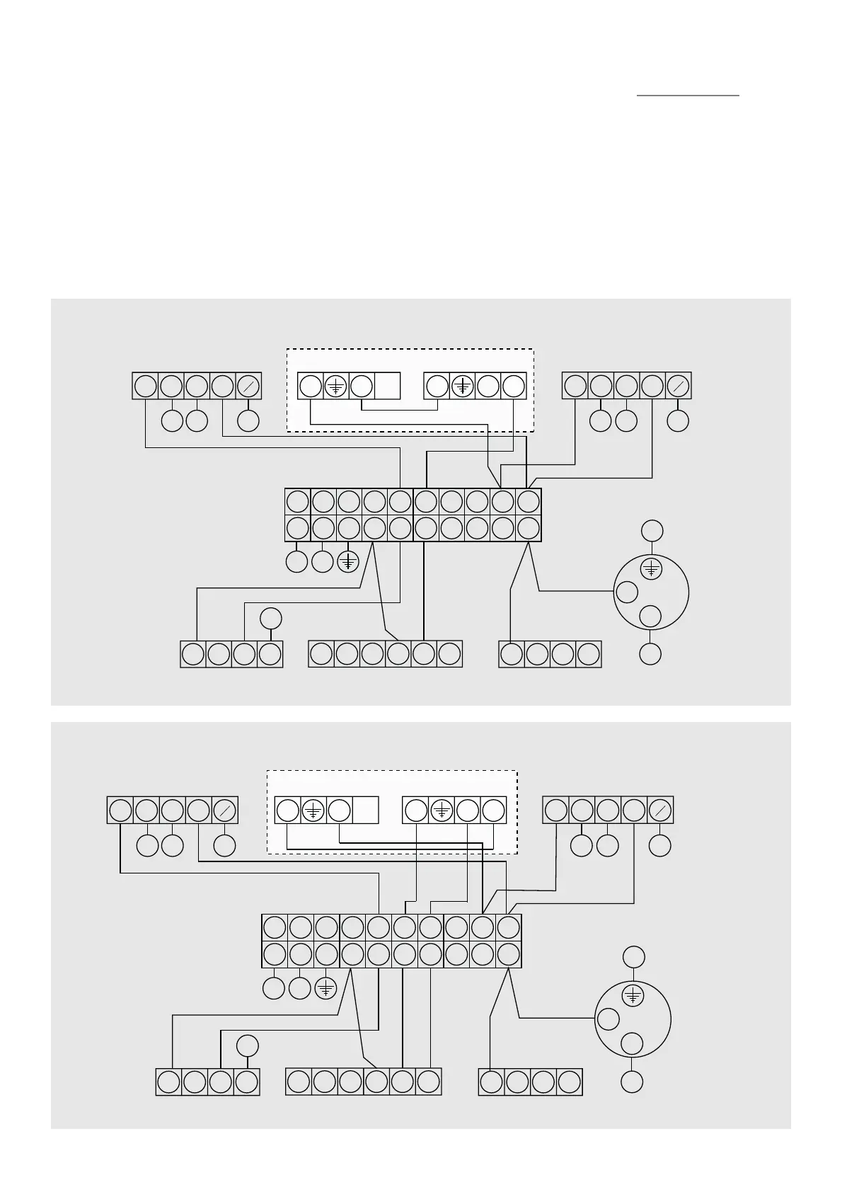
TYPICAL SCHEMATIC WIRING DIAGRAMS
3 PORT (HTG)
W
GBIO
G
Y
7
2
33
2
1
DUAL STAT
2 PORT (DHW)
C
2C
2
1
Br
GBlO
G
Y
1 2 3 4 5 6 7 8 9 10
1 2 3 4 5 6 7 8 9 10
WIRING CENTRE
3
L
N
2
L N
1 2 3 4
L N E 4 5 6
1 2 3 4
2
5A SUPPLY
ROOM STAT PROGRAMMER
BOILER
PUMP
WIRING DIAGRAM THREE PORT MID POSITION VALVE (Y-PLAN) + TWO PORT VALVE
WIRING DIAGRAM 2 x TWO PORT ZONE VALVES (S-PLAN)
2 PORT (HTG)
Br
GBIO
G
Y
1
2
33
2
1
DUAL STAT
2 PORT (DHW)
C
2C
2
1
Br
GBlO
G
Y
1 2 3 4 5 6 7 8 9 10
1 2 3 4 5 6 7 8 9 10
WIRING CENTRE
3
L
N
2
L N
1 2 3 4
L N E 4 5 6
1 2 3 4
2
5A SUPPLY
ROOM STAT PROGRAMMER
BOILER
PUMP
The diagrams shown relate to the components listed. Other components and other manufacturers’ components may vary in
their wiring requirements, particularly thermostats. Always refer to manufacturers’ instructions which may override the detail
in order to function correctly.
16
STAINLESS UV
UNVENTED HOT WATER CYLINDERS
 Loading...