CHAPTER 4
RAM Expansion
The Expansion Slots 43
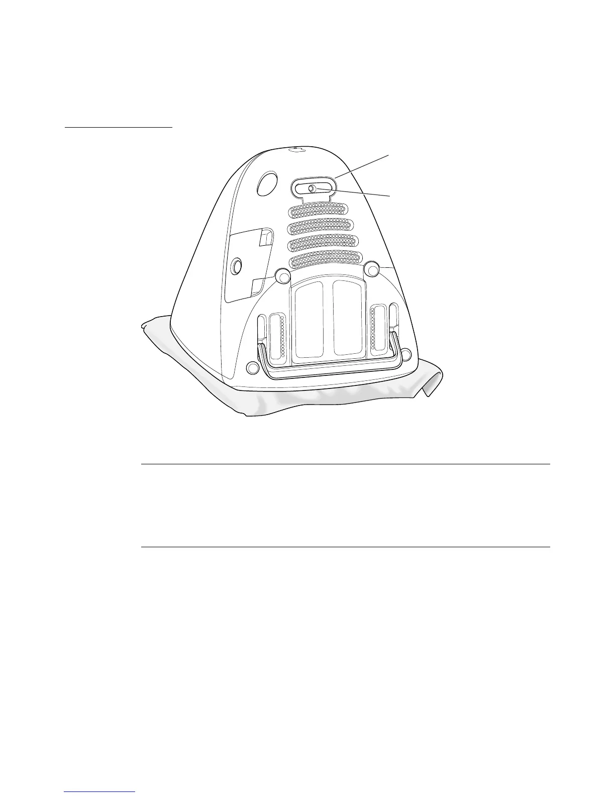
Figure 4-1 Bottom view showing bottom cover handle
Removing the bottom cover 4
The bottom cover is held in place by a retaining screw located on the bottom
cover and accessible through the opening in the handle. After removing the
screw, the user can remove the cover by pulling up and out on the handle.
Unfastening the Cables 4
Several signal cables are connected to the back of the logic board assembly, as
shown in Figure 4-2. Those must be disconnected and freed from their clamps.
Once the cables and clamps are disconnected, the user should position the
cables to either side of the logic board assembly, as shown in Figure 4-3.
Handle
Retaining screw