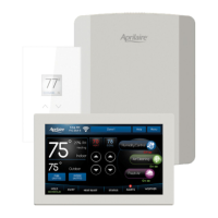
LAYOUT
6000 SERIES HUB
TERMINALS
1. HVAC – HVAC connection.
2. JUMPER – RH/RC Jumper.
3. ZONE 1 CONTROL – 6000 Series Control connection.
4. ZONE 2 CONTROL – 6000 Series Sensor 2 connection.
5. ZONE 3 CONTROL – 6000 Series Sensor 3 connection (3Zone
models only).
6. DAMPER 1 – Zone 1 damper connection.
7. DAMPER 2 – Zone 2 damper connection.
8. DAMPER 3 – Zone 3 damper connection (3 Zone models only).
9. REMOTE SENSORS DAT (Discharge Air Temperature).
10. REMOTE SENSORS ODT (Outdoor Air Temperature).
11. REMOTE SENSORS RAT (Returning Air Temperature).
12. POWER – System power connection 24VAC.
13. HUM/AUX – Humidifier (AUX is for future upgrades).
14. DEHUM – Dehumidifier.
15. VENT – Ventilation.
LEDS
16. POWER – Green: 24VAC present. Flashing: Not connected to 6000
Series Control.
17. EM HEAT – Yellow: Emergency heating is active.
18. HEATING – Green: Heating is active.
19. COOLING – Green: Cooling is active.
20. FAN – Green: Fan output is active.
21. HUM/AUX – Green: Humidification output is active (AUX is for future
upgrades).
22. DEHUMIDIFIER – Green: Dehumidification output is active.
23. VENTILATION – Green: Humidification output is active.
24. ZONE 1 – Green: Damper is open. Red: Damper is closed.
25. ZONE 2 – Green: Damper is open. Red: Damper is closed.
26. ZONE 3 – Green: Damper is open. Red: Damper is closed. (3 Zone
models only)
BUTTON
27. INSTALLER TEST BUTTON – See page 24.
16
17
18
19
20
21
22
23
24
25
26
8
7
6
11
9
1
2
12
3
4
5
13
15
90-2406
5
 Loading...