English 98 English
MOUNTING THE OUTDOOR TEMPERATURE SENSOR
1. Drill a 3/8" diameter hole in the duct of the fresh air inlet hood.
2. Install the outdoor temperature sensor into the duct and use metal foil tap to secure it in place
and seal the opening. Run the wire toward the outside wall.
3. Secure ductwork to the inlet hood duct while allowing the wire of the sensor to extend outside
of the insulation. Tape and/or mastic the duct as needed and properly insulate.
3/8" DIA
HOLE
USE METAL FOIL
TAPE TO SECURE
SENSOR TO DUCT
INSULATED
FLEX DUCT
ENSURE PROPER
SEAL TO PREVENT
CONDENSATION
OUTDOOR
TEMPERATURE
SENSOR
90-2265
WIRING
Disconnect power to the HVAC system to prevent electrical shorts while wiring.
1. Run a 2-conductor cable from the control to the outdoor temperature sensor (if installed) and
wire to the controller ODT terminals.
2. Run an 8-conductor thermostat cable from the control to the HVAC equipment. Wire the
controller to the HVAC equipment in accordance with FIGURE 1 or FIGURE 2 diagram below.
Contact customer service if wiring assistance is needed for other equipment configurations.
3. Run a 2-conductor cable from the control to either the damper in Model 8126X installations or
to the Fresh Air Ventilator and wire according to FIGURE 3 (Model 8140NC or Model 8145NC),
FIGURE 4 (Model 8142NC), FIGURE 5 (Model 8144NC) or FIGURE 6 (damper).
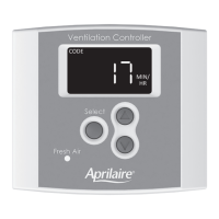
MODEL 8120X DIGITAL VENTILATION CONTROL
Y = COOLING
W = HEAT
GS = FAN INPUT
GH = FAN OUTPUT
FIGURE 1 – WIRING TO FURNACE
 Loading...