AIR IS PULLED
FROM THE MAIN
RETURN DUCT
AIR IS DISCHARGED
TO THE SUPPLY DUCT
MODEL E100
0.6" W.C. MAX
MODEL E080
0.4" W.C. MAX
C
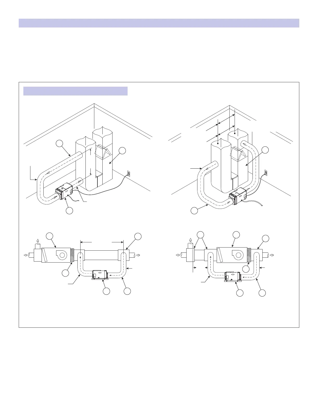
FIGURE 15: FOUR INSTALLATION CONFIGURATIONS
A. DEHUMIDIFIER
B. 10” DIAMETER INSULATED DUCT
C. HVAC/FURNACE
D. PLENUM BOX
E. AIR HANDLER
F. PLENUM BOX OR Y-FITTING
G. FILTER
H. CONDENSATE PAN
6
FEET
MIN
AIR IS PULLED
FROM THE MAIN
RETURN DUCT
AIR IS DISCHARGED TO
THE MAIN RETURN DUCT
B
C
RETURN-TO-RETURN
BASEMENT INSTALLATION
RETURN-TO-RETURN ATTIC INSTALLATION
RETURN-TO-SUPPLY
BASEMENT INSTALLATION
RETURN-TO-SUPPLY ATTIC INSTALLATION
6 FEET MIN
AIR IS PULLED
FROM THE
DUCT
AIR IS DISCHARGED TO
THE MAIN RETURN DUCT
G
E
F
90-1886 90-1887
90-1888
24"
MIN
AIR IS PULLED
FROM THE MAIN
RETURN DUCT
AIR IS DISCHARGED
TO THE SUPPLY DUCT
D E
F
G
90-1889
DUCTING THE DEHUMIDIFIER INLET AND OUTLET TO THE HVAC SYSTEM
• Use when both sides of the duct system are accessible
(see FIGURE 15).
• When ducting from return to supply, the HVAC blower does
not need to be running when the dehumidier is running.
• When ducting return to supply, allow adequate space
(24” min) before the rst branch duct to ensure the warm
dehumidied air is thoroughly mixed with the HVAC system air.
• When ducting from return to return, wire the dehumidier to
the HVAC system as shown in FIGURE 20 to ensure the HVAC
blower runs when the dehumidier is operating.
• Wire the dehumidier to the HVAC system (see FIGURE 20
for exact wiring) and set up the dehumidier to be disabled
when the AC is running.
10
 Loading...