6
FEET
MIN
A
B
C
D
E
F
G
G
+ - A B ODT VENT
DHDH
GhRf Cf Gs YW
DEH
FLOAT
Switch
B C D
E
A
F
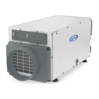
FIGURE 28: WHOLE-HOME PRIMARY ZONE INSTALLATION
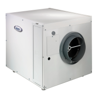
FIGURE 29: TWO-ZONE WIRING ON-BOARD CONTROL
A. RETURN FROM SECONDARY ZONE
B. NORMALLY CLOSED DAMPERS
C. RETURN DUCT
D. TO/FROM PRIMARY ZONE
A. FLOAT SWITCH
B. REMOTE
C. SENSOR
D. DAMPERS
E. SUPPLY DUCT
F. SUPPLY TO SECONDARY ZONE
G. NORMALLY OPEN DAMPER
E. HVAC EQUIPMENT
F. 24 VAC (40 VA MIN.)
G. NORMALLY CLOSED (PRIMARY ZONE)
H. NORMALLY OPEN (SECONDARY ZONE)
90-1875
90-1896
INSTALLER SETUP
Enter the setup menu if:
• the dehumidier is ducted to the HVAC system
• an external or remote control will be used
• ventilation or zoning will be used
1. Plug unit in and turn power switch ON (if equipped).
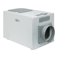
2. The onboard control screen should display OFF. If not OFF,
press the ON/OFF button to turn the unit OFF.
NOTE: If the display backlight is not on, the rst button press
(any button) will only turn on the backlight. Press the button a
second time to achieve function.
3. Hold the MODE button on the onboard control for 3 seconds
to enter the installer setup menu.
4. Navigate through the following screens to set up the
dehumidier for the installed application.
5. Use the or button to select items and use the MODE
button to switch to the next setup option. To exit the installer
setup, scroll through all options using the MODE button.
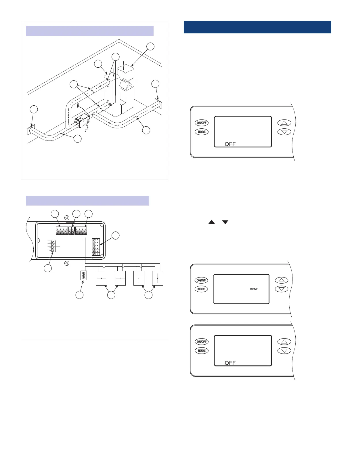
6. After the installer setup options have been completed, the
word DONE will blink for 3 seconds and the control will return
to the OFF screen.
16
 Loading...