A
B
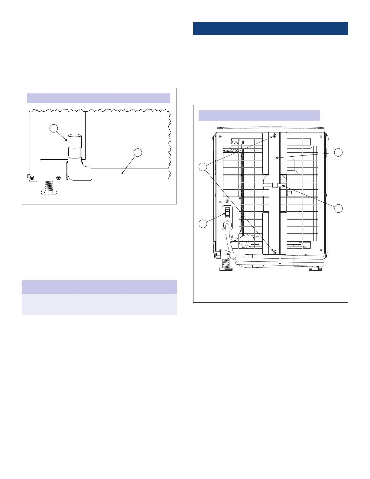
FIGURE 7: CAPPED DRAIN ACCESS FOR CLEANING PROCESS
90-2693
A. CAP
B. CONDENSATE DRAIN LINE
PREPARING THE UNIT FOR INSTALLATION
IMPORTANT: Cut the strap securing the compressor shipping
support bracket and remove the strap and shipping bracket
(see FIGURE 8).
1. Clip off and remove the plastic straps securing the
compressor to the shipping bracket.
2. Remove the two screws securing the shipping bracket to
the housing. Remove and discard the shipping bracket, and
reinstall the two screws in the dehumidier.
A
B
D
C
FIGURE 8: PREPARING THE UNIT FOR INSTALLATION
90-1908
A. PLASTIC STRAP
B. SCREWS
C. SHIPPING BRACKET
D. ON/OFF POWER SWITCH
(SELECT MODELS)
4. Reinstall the drain insert by gently placing the tip into the
drain opening and rocking the insert downwards into place
(see FIGURE 6). When inserted properly, the top of the drain
insert will be at the same height as the lter guide channel.
5. If the dehumidier has clear exible drain tubing, look for
excess buildup in the drain line that might prevent water
ow, and replace as needed. Clear, smooth, exible 3/4”
Inside Diameter (ID) drain tubing is available in most
hardware stores or Do-It-Yourself (DIY) retail stores.
NOTICE
Running the dehumidier without the drain insert can lead
to condensate leaks.
2. Clean the accessible portion of the drain pan and the drain
insert using a mild detergent.
3. If the drain has a capped tee or elbow to allow cleaner to
be poured directly in the drain, remove the cap and pour
approximately one cup of white vinegar into the tube (see
FIGURE 7). If there is no visible access to the drain line from
outside of the dehumidier, pour approximately one cup
of vinegar into the drain pan of the dehumidier where the
drain insert was located.
6
 Loading...