A
B
A
B
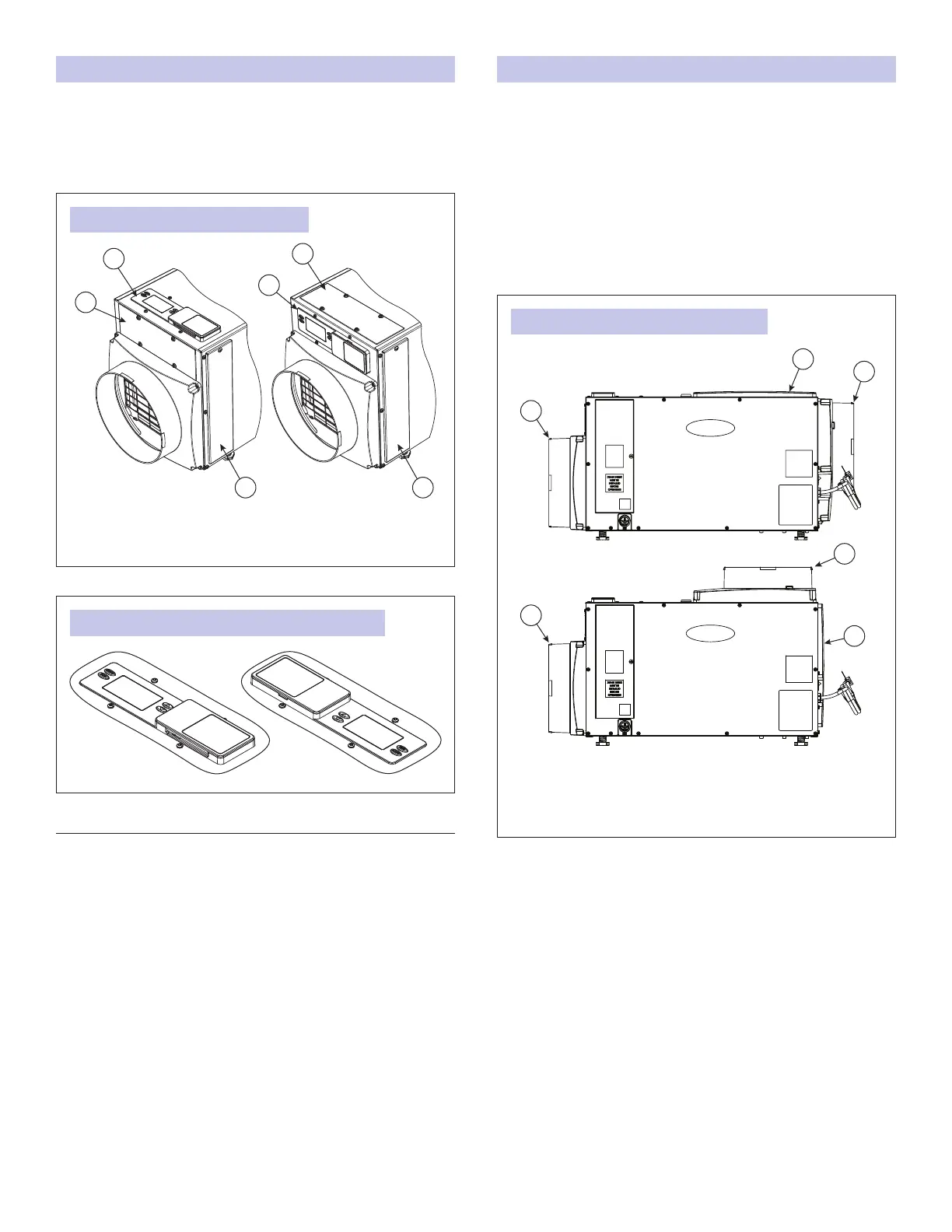
FIGURE 9: USER INTERFACE LOCATION
FIGURE 10: USER INTERFACE ROTATED 180 DEGREES
90-1884
90-2525
A. USER INTERFACE DOOR
B. USER INTERFACE
C. FILTER ACCESS DOOR
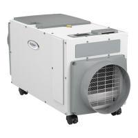
REPOSITIONING THE USER INTERFACE FOR THE APPLICATION
Locate the onboard user interface on the top of the
dehumidier or at the front of the dehumidier if the user
interface cannot be seen/accessed in the top orientation. It
may also be rotated 180 degrees in either orientation (see
FIGURE 10).
MOVING THE CONTROL
1. Remove the front user interface door.
2. Remove the lter access door and lter.
3. Detach the onboard user interface by removing the four (4)
screws around the user interface.
NOTE: Use one hand to support the bottom of the onboard
user interface when removing.
4. Keep the user interface in the unit and relocate to the front
access hole.
5. Secure the user interface with the same four screws used to
attach the user interface to the top of the unit.
6. Secure the user interface door to the top of the unit.
A
B
C
C
B
A
FIGURE 11: FULLY DUCTED INSTALLATIONS
90-2592
A. INLET DUCT COLLAR
B. OUTLET COVER
C. OUTLET DUCT COLLAR WITH BACK DRAFT DAMPER
END DISCHARGE
TOP DISCHARGE
INSTALLING THE DUCT COLLARS
• Use the screws in the parts bag to attach the duct collars to
the inlet and outlet of the dehumidier. The outlet collar has a
backow damper.
• The outlet duct collar may be attached to the top or end of
the unit. Move the outlet cover to the location not being used
(see FIGURE 11).
• Make sure there are no bends in the ductwork coming off
the outlet for a minimum of 4”. This precaution will ensure
that the ductwork will not interfere with the backow damper
function.
7
 Loading...