5
Műszaki tudnivalók
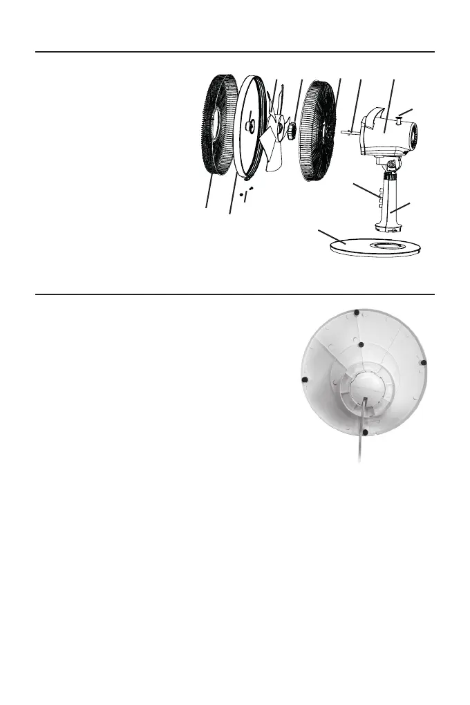
Összeszerelés
1. A talpat (1) rögzítsük a fő egységhez (3): a tápká-
belt vezessük a talpban kialakított lyukba, a talpat
az ábrán látható módon illesszük a fő egységre,
majd a talpat annak elforgatásával rögzítsük a fő
egységen.
2. A tápkábelt a kialakított horonyban vezessük ki.
3. Az óramutató járásával egyező irányba forgatva
csavarjuk le a ventilátort rögzítő anyát (10) a mo-
tor tengelyről (6).
4. Az óramutató járásával ellentétes irányba forgatva
csavarjuk le a hátsó rácsot rögzítő anyát (8) a mo-
tor tengelyről (6).
5. A hátsó rácsot (7) illesszük a motor tengelyre (6)
ügyelve, hogy a három rögzítőcsap beleüljön a hát-
só rácson kialakított fogadó lyukakba. A hátsó rács rögzítő anyát (8) az óramuta-
tó járásával egyező irányba elforgatva rögzítsük a hátsó rácsot.
6. Illesszük a ventilátort (9) a motor tengelyre (6), majd a ventilátor rögzítő anyát
(10) az óramutató járásával ellentétes irányba forgatva rögzítsük a ventilátort.
7. A rögzítőlemezen (11) lazítsuk meg a biztonsági csavart (13), majd helyezzük
azt a hátsó rácsra (7).
8. Az elülső rácsot (12) helyezzük a hátsó rácshoz (7) ügyelve, hogy az elülső rá-
cson a központi csapon található logó vízszintesen, a padlóval párhuzamosan
fusson: a rács és a gyűrű egymáshoz rögzítése ebben az állásban kivitelezhető.
Ellenőrizzük, hogy az elülső rács stabilan rögzüljön az elülső rácshoz.
9. A megfelelő helyzetet megtalálva húzzuk meg a rács biztonsági csavarját (13).
1. Talp
2. Kezelőpanel
3. Fő egység
4. Forgó mozgás gomb
5. Motor
6. Motor tengely
7. Hátsó rács
8. A hátsó rács rögzítő anya
9. Ventilátor
10. Ventilátor rögzítő anya
11. Rögzítőlemez
12. Elülső rács
13. Biztonsági csavar
11
1. Base
2. Control panel
3. Main body
4. Oscillation knob
5. Motor
6. Motor shaft
7. Back grille
8. Lock ring of the back
grille
9. Fan
10. Lock ring of the fan
11. Lock ring
12. Front grille
13. Safety screw
1
2
3
4
67
89
10
11
12
13
5
1. Mount the base (1) on the main body(3):
insert the power code into the hole of the
base, place the base on the main body as
shown in gure and x by rotating it clockwise.
2. Fix the power cord into their slots.
3. Unscrew the lock ring of the fan (10) from
the motor shaft (6) by turning it clockwise.
4. Unscrew the lock ring of the back grid
(8) from the motor shaft (6) by rotating it
counterclockwise.
5. Insert the back grille (7) on the motor shaft
(6) making sure that the three locking pins
are placed into their holes of the back grille.
Screw the lock ring of the back grille (8) by
turning it clockwise.
6. Insert the fan (9) on the motor shaft (6) and fasten the proper lock ring
(10) by rotating counterclockwise.
7. Loosen the safety screw (13) from the lock ring (11) and place it on
the back grille (7).
Assembling
Technical informations
11
1. Base
2. Control panel
3. Main body
4. Oscillation knob
5. Motor
6. Motor shaft
7. Back grille
8. Lock ring of the back
grille
9. Fan
10. Lock ring of the fan
11. Lock ring
12. Front grille
13. Safety screw
1
2
3
4
6789
10
11
12
13
5
1. Mount the base (1) on the main body(3):
insert the power code into the hole of the
base, place the base on the main body as
shown in gure and x by rotating it clockwise.
2. Fix the power cord into their slots.
3. Unscrew the lock ring of the fan (10) from
the motor shaft (6) by turning it clockwise.
4. Unscrew the lock ring of the back grid
(8) from the motor shaft (6) by rotating it
counterclockwise.
5. Insert the back grille (7) on the motor shaft
(6) making sure that the three locking pins
are placed into their holes of the back grille.
Screw the lock ring of the back grille (8) by
turning it clockwise.
6. Insert the fan (9) on the motor shaft (6) and fasten the proper lock ring
(10) by rotating counterclockwise.
7. Loosen the safety screw (13) from the lock ring (11) and place it on
the back grille (7).
Assembling
Technical informations
 Loading...