13
(see image at last page)
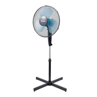
1. Front grille
2. Lock ring of the fan
3. Safety screw of the fan
4. Fan
5. Lock ring of the back grille
6. Back grille
7. Motor shaft
8. Oscillation knob
9. Motor
10. Control panel
ASSEMBLING
11. Main body screw
12. Small decorative base
13. Adjustment rod
14. Height adjustment knob
15. Base rod
16. Screws for xing the base
rod (4 pieces)
17. Cross base
A-B. Locking pin for the rear
grille
1. Unscrew the screws (16) from the two parts which form the basis of
the cross (17).
2. Fit the two parts which form the basis of the cross (17) as is shown in
the picture.
3. Unscrew the height adjustment knob (14) from the base rode (15) and
insert the small decorative base (12).
4. Pull out the adjustment rod (13) from the base rod (15) then tighten the
height adjustment knob (14) on the base rod (15).
5. Tighten the base rod (15) with the screws (16) previoulsy unscrewed
from the cross base (17).
6. Loosen the screw of the main body (11).
7. Insert the main body on the adjustment rod (13). Tighten the screw
(11) for xing it.
8. Unscrew the locking ring of the rear grille (5) from the motor shaft (7)
by turning it counterclockwise.
9. Insert the rear grille (6) on the motor shaft (7) making sure that the
handle on the back is facing upwards and the locking pins (A-B) are in
the vertical holes of the rear grille. Screw the locking ring (5) by turning
it clockwise.
10. Place the blade (4) on the motor shaft (7) and secure it by turning
counterclockwise the locking ring (2).
11. Open the clips of the front grille (1) and place it on the back grille (6)
making sure that the logo on the central stud is placed horizontally,
parallel with the oor.
13. Find the proper position to lock the clips and insert the safety screw
of the grille (3).