461306971 (RS-000)
18
S
Q
A
T
8
GB 6. INSTALLER INSTRUCTIONS
ELECTRICAL CONNECTION
Electrical connection must be carried out
in accordance with current standards and
normative.
Before connecting the oven check out the
following list:
• The system and electrical sockets amperage is
adequate for the appliance maximum power (see
data label affi xed on the back of the oven and in the
appliance handbook)
• The socket or system has an effective earth
connection in accordance with current standards
and prescriptions of the law. All responsibility is
disclaimed if this is not complied with.
• When positioning the appliance, make sure that the
plug or multipolar switch are easily accessible.
When connecting to the mains with a socket:
• Fit a standard plug, suitable for the load, which is
indicated on the rating plate, to the power cable.
Connect the wires making sure they match the
indications below. Pay attention to the earth wire,
which must be longer than the phase wires:
letter
L
(phase) = brown wire
letter
N
(neutral) = blue wire
symbol
(earth) = green/yellow wire
• The power cable must be laid far from heat sources
and its temperature should stay below 75°C.
• Avoid using adapters or shunts as they could cause
false contacts resulting in hazardous overheating.
When connecting directly to the mains:
• Install a multipolar switch that can withstand the
appliance’s load, with a minimum opening between
the contacts of 3 mm. Remember that the earth wire
must not be cut out by the switch.
MAINTENANCE
Before replacing any spare parts it is vital to
disconnect the appliance from the electricity
mains.
REPLACING ELECTRICAL COMPONENTS
• To replace the oven lamp please refer to instructions
on page 15.
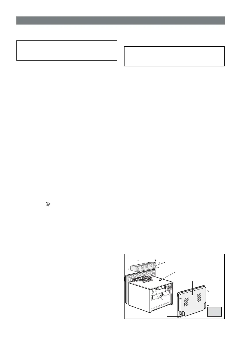
• To access other electrical components the oven
will have to be removed from its housing unit by
unscrewing it (V) (see fi g. 7). Oven extraction allows
access to the terminal board (T) (fi g. 8).
• If the power cable needs replacing always keep
the earth wire longer than the phase wires
and do follow all instructions given in the
“ELECTRICAL CONNECTION” section.
• Remove the rear protection panel (Q) to have access
to the gear motor, heating elements, temperature
limiting device and lamp holder (fi g. 8).
• To change the lamp-holder (P) (fi g. 5), unscrew the
protective glass cap (C), force the tabs of blockage
(M) and take the lamp-holder toward the outside of
the oven.
• To replace the thermostat, the commutator, the
programmer and the indicator lights, remove
protection box (S) (fi g. 8). Remove the knobs and
undo the screws underneath to front panel to free
the components that need replacing.
 Loading...