Connected
Connected
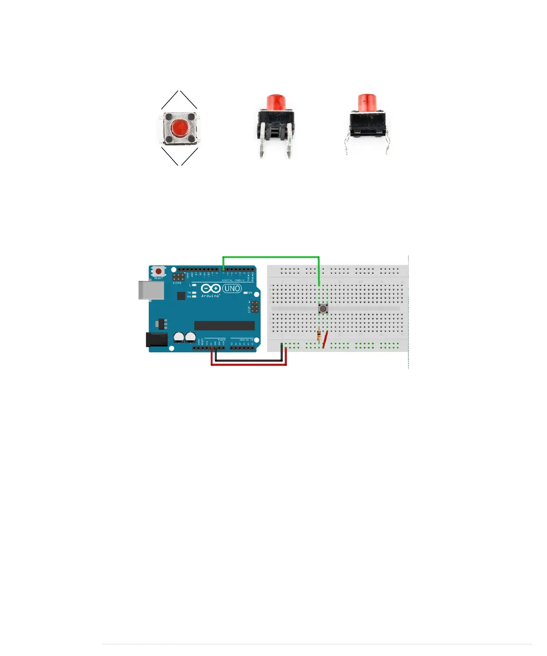
Top Front Side
The following picture shows a simple circuit using a pushbutton. Connect
pin 7 (chosen completely arbitrarily) to the pushbutton, and connect the
pushbutton via a 10kΩ resistor to ground. Then connect the 5-volt power
supply to the other pin of the button. Make sure the pushbutton’s orientation
is right. Its connected pins have to bridge the gap of the breadboard.
All in all, this approach seems straightforward, but why do we need a resistor
again? The problem is that we expect the pushbutton to return a default
value (
LOW
) in case it isn’t pressed. But when the button isn’t pressed, it would
be directly connected to ground and would flicker because of static and
interference. Only a little bit of current flows through the resistor, and this
helps prevent random fluctuations in the voltage at the input pin.
When the button is pressed, there will still be 5 volts at the Arduino’s digital
pin, but when the button isn’t pressed, it will cleanly read the connection to
ground. We call this a pull-down resistor; a pull-up resistor works exactly the
other way around. That is, you have to connect the Arduino’s signal pin to
power through the pushbutton and connect the other pin of the pushbutton
to ground using a resistor.
Now that we’ve eliminated all this ugly unstable real-world behavior, we can
return to the stable and comforting world of software development. The follow-
ing program checks whether a pushbutton is pressed and lights an LED
accordingly:
report erratum • discuss
Working with Buttons • 49
www.it-ebooks.info
 Loading...