4
manuale d’uso user’s manual
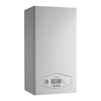
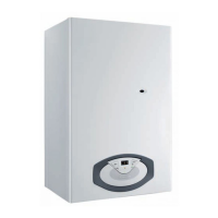
Pannello comandi
Legend:
1. Display
2. RESET button
3. Red LED (illuminated = boiler lockout)
4. Heating System Pressure Gauge
5. Selector knob for Summer/Winter Central Heating
Temperature Adjustment Knob
6. Programming “-” key
7. Menu/Ok button
8. Esc button
9. Programming “+” key
10. Domestic Hot Water adjustment knob (
11. Time clock (optional)
12. ON/OFF Switch
13. “COMFORT” Function L.E.D (comfort function activated)
14. Green led (auto function activate)
15. Auto button
16. COMFORT button
Control Panel
1
2
3
4
5
6
7
16
15
14
13
12
11
10
9
8
Legenda:
1. Display
2. Tasto Reset
3. LED Rosso
(illuminato = segnalazione di Blocco)
4. Idrometro
5. Selettore Estate/Inverno
Manopola regolazione temperatura riscaldamento
6. Tasto Programmazione “-”
7. Tasto Menu/Ok
8. Tasto Esc
9. Tasto Programmazione “+”
10. Manopola regolazione temperatura sanitario
11. Predisposizione orologio programmatore (optional)
12. Tasto ON/OFF
13. Led Giallo (Funzione Comfort attiva)
14. Led verde (Funzione Auto Attivata)
15. Tasto Auto
16. Tasto Comfort
ATTENZIONE
L’installazione, la prima accensione, le regolazioni di manutenzione
devono essere eff ettuate, secondo le istruzioni, esclusivamente da
personale qualifi cato.
Un’errata installazione può causare danni a persone, animali o cose,
nei confronti dei quali il costruttore non è considerato responsabile.
WARNING
Installation, fi rst ignition and maintenance work must be performed
by qualifi ed personnel only, in accordance with the instructions
provided.
Incorrect installation may harm individuals, animals or property; the
manufacturer will not be held responsible for any damage caused as
a result.

 Loading...
