WIRING SCHEME FOR 2 X 2 PORT MOTORISED VALVES
T6360B
ROOM
THERMOSTAT
14
35
22
OR
CM 41
CM 51
A
B
1
5
V4043H
HEATING VALVE
BROWN
5
BLUE
2
GREY
1
ORANGE
10
GREEN/YELLOW
3
V4043H
HOT WATER VALVE
BROWN
8
BLUE
2
GREY
1
ORANGE
10
GREEN/YELLOW
3
Honeywell ST 699B 1002
63 N L
Link L-5-8
ST 6400/ST 6300 ST 6200 3 4 N L
Drayton Tempus 7 3 4 N L
Horstmann 425, 525, 527
14 EN L
Link L-2-5
Landis & Gyr RWB2
34 N L
Glowworm Mastermind
Landis & Gyr RWB20
34 N L
Microgyr
Potterton Miniminder 3 4 N L
Potterton EP2000/3000 - 3 4 N L
Link L-5 EP2001/3001
Randall 102/102 E 1 2 E 5 6
Link 3-6
Randall 4033
42 E7 6
Link 1-6
Randall 701, 702
31 EN L
Link L-6-5
Sangamo M5 1 8 E 4 3
Link 1-6
Sangamo 410 Form 1
18 E4 3
Link 3-6
PROGRAMMER
64321
Pegler Sunvic
25 EN L
SP 50/100 (Link L-3)
Switchmaster
14 N L
Symphony, Sonata
Switchmaster 400, 600 3 1 N L
SWITCHMASTER 805, 900
31 N L
Sunvic ET 1451
74 E1 2
Link 2-3-6
Sunvic DHP 2201 6 3 E 1 2
Towerchron FP
610 2 1
Link 1-5/4-7-9
Towerchron MP
610 2 1
Link 1-4/6-11
Towerchron 2000 HW HTG
NL
ON ON
ACL LS522, LS722 3 4 N L
Randall 922, 972
36 EN L
Link L-2-5
Randall 3020 P
42 EN L
and 3060
PROGRAMMER
64321
1
P
Cylinder
thermostat
Thermal
cut-out
ELEMENT
3 kW 240V
~
Thermal
cut-out
Thermostat
1
8
6
Not
used
L1
240V~
N
P
2
1 P
2
240V
MAINS INPUT (3 AMP)
L1
N2
E3
240V
MAINS INPUT (13 AMP)
E
L
N
• 1
• 2
• 3
• 4
• 5
• 6
• 7
• 8
• 9
• 10
TYPICAL
JUNCTION BOX
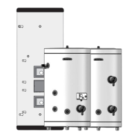
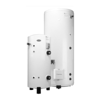
INDIRECT SYSTEMS
For models up to 300 litres a mains supply of 240V, 3kW (13 amps) will be
required for the direct immersion heater. heat resistant cable, round 3 core
2.5mm
2
(to BS) must be used. For High Capacity 500 litre models consult
the wiring diagram on the reverse of the inspection panel.
For indirect controls a 240V, 3 amp supply is required.
On Comfort models the indirect thermostat is factory fitted, for Contract and
High Capacity models it is necessary to fit the thermostat using P.T.F.E tape
(Please consult the label on the face of the unit for the correct location in
both cases).
The cables must be clamped in position (as previously stated) and the
control thermostat should be set at 60°C for the reasons above. In addition
to the thermostat there is a thermal cut-out should the thermostat fail. Refer
to
FIG. 2.14 and FIG. 2.15 for full wiring instructions.
15
FIG. 2.14
Basic Boilers (see Page 17) L E N L N E
Baxi Solo 30PF To 80PF
PL SL E N L L N E
and 30RS to 60RS
Glowworm Economy Plus
7 SL E N L L N E
(remove link SL-9)
Glowworm Spacesaver KFB50
9 12 E N L L N E
(remove link 12-7)
Glowworm Ultimate SS
P SL E N L L N E
(remove link SL - 4)
Glowworm Fuelsaver 100FF
P SL E N L L N E
(remove link 7 - 12)
Halstead Best range 2 1 E N L L N E
Halstead Balmoral range 9 6 E N 12 L N E
Halstead Blenheim range LP 2 E N L L N E
Ideal Mexico Super 2 PL LB E N L L N E
Myson Apollo
PL ON E N L L N E
(remove all links)
Potterton Profile/Suprima PL SL E N L L N E
For ARISTON, Vaillant, Vokèra,
Burco Maxol and other makes, refer
to manufacturers instructions.
BOILER PUMP
9
10 3 2 1 9 10
2
3
Based on Honeywell Controls
 Loading...