Chapter 1: Introduction
2X-A Series Installation Manual 13
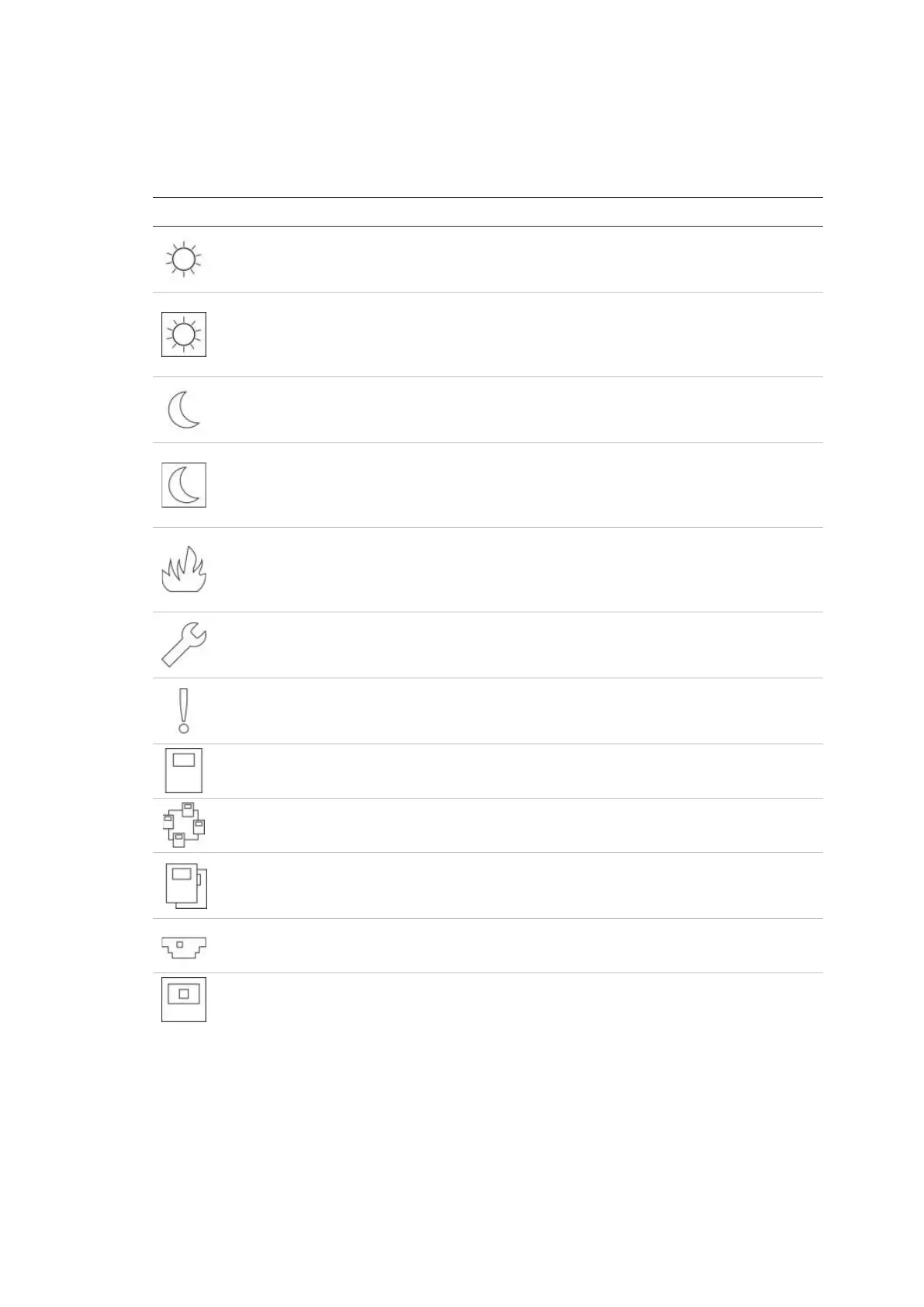
Icons displayed on the LCD
Icons displayed on the LCD are shown below.
Table 7: LCD icons and descriptions
Description
Day mode (network)
This icon indicates that the primary sensitivity mode
setting for control panels in the fire network is day
mode.
Day mode (control panel)
This icon indicates that the sensitivity mode for the local
control panel is day mode. Other control panels in the
fire network may have a different sensitivity mode
setting.
Night mode (network)
This icon indicates that the primary sensitivity mode
setting for control panels in the fire network is night
mode.
Night mode (control panel)
This icon indicates that the sensitivity mode for the local
control panel is night mode. Other control panels in the
fire network may have a different sensitivity mode
setting.
Fire alarms [2]
The number beside this icon indicates the number of
zones with an active fire alarm. Alarm information for
the first and last zones to report an alarm is displayed in
the LCD message area.
Faults [2]
The number beside this icon indicates the number of
active faults. Additional information is available by
pressing F1 (Show Events).
Conditions [2]
The number beside this icon indicates the number of
active system conditions. Additional information is
available by pressing F1 (Show Events).
Stand-alone
This icon indicates that the control panel is not
connected to the fire network.
Networked
This icon indicates that the control panel is connected
to the fire network.
Repeater
This icon indicates that the control panel is configured
to operate as a repeater and is connected to the fire
network.
Detector alarm [1]
This icon indicates a detector alarm.
Manual call point alarm [1]
This icon indicates a manual call point alarm.
 Loading...