I
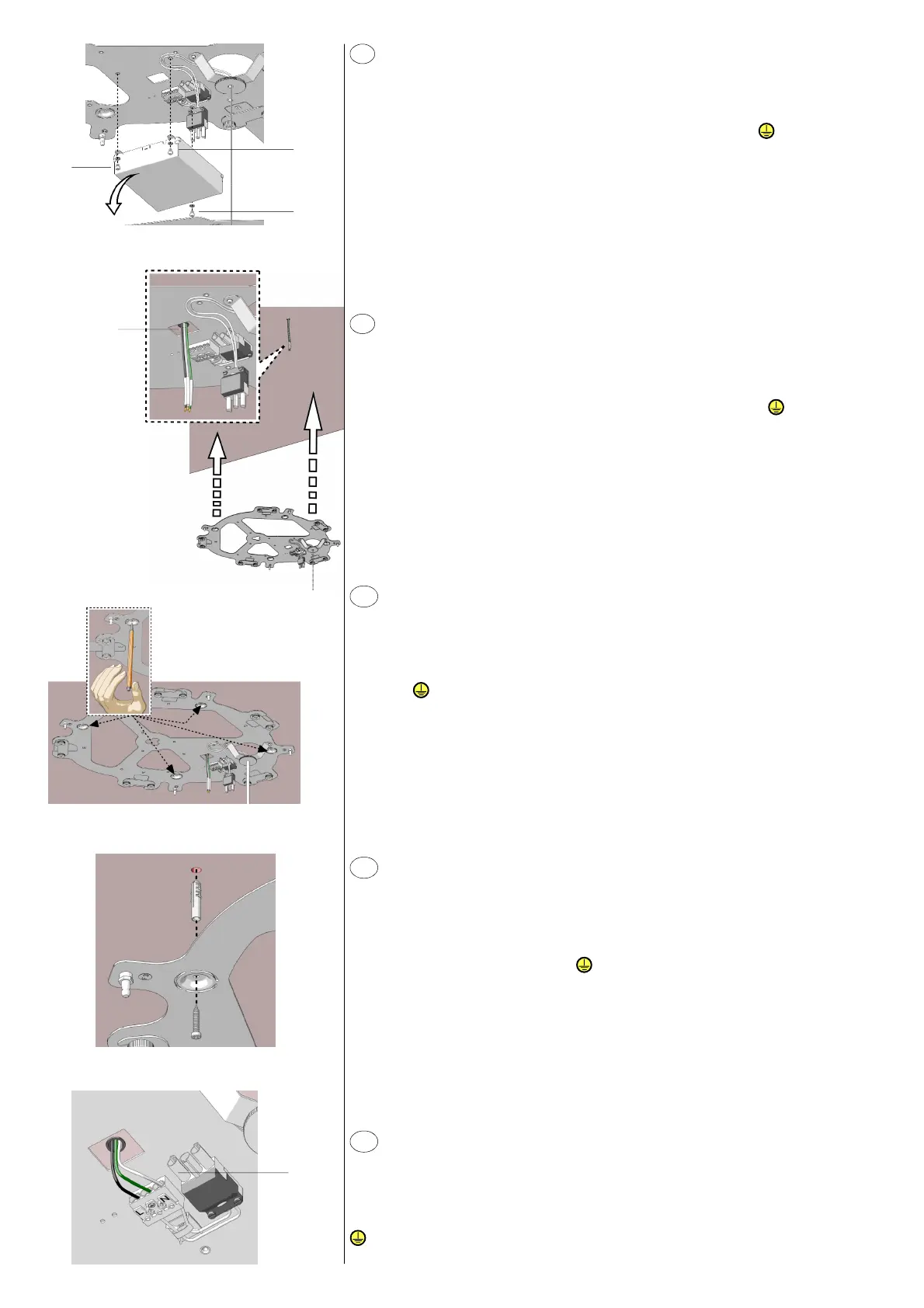
Smontare dalla struttura centrale la copertura morsetti (fig. 3), svitando le tre viti Y. Dopo aver
deciso l’orientamento della composizione, portare la struttura centrale a soffitto posizionando
lo scasso A in corrispondenza del punto luce (fig. 4). Segnare la posizione dei tasselli (fig. 5).
Forare e fissare la struttura centrale (fig. 6). Eseguire i collegamenti elettrici all’apposito morsetto
B collegando il cavo di terra al morsetto contrassegnato con il simbolo (fig. 7).
}
A
B
}
fig. 3
fig. 5
fig. 6
fig. 7
~
~
Y
Y
fig. 4
Désassembler la couverture bornes de la structure centrale (fig. 3), en dévissant les trois vis Y.
Après avoir décidé l’orientation de la composition, porter la structure centrale contre le plafond
en positionnant l’ouverture A près du point de lumière (fig. 4). Marquer la position des
chevilles (fig. 5). Percer et fixer la structure centrale (fig. 6). Brancher à la borne adéquate B en
connectant le câble de mise à la terre à la borne marquée par le symbole (fig. 7).
Remove the terminal cover from the central structure (fig. 3) by unscrewing the three
screws Y. After determining the orientation of your composition, bring the central structure
towards the ceiling and position opening A near the light point (fig. 4). Mark the position
of the screw anchors (fig. 5). Drill and fix the central structure (fig. 6). Carry out the electrical
connections to the proper terminal B and connect the earth cable to the terminal marked
by symbol (fig. 7).
Die drei Schrauben Y herausschrauben und die Bedeckung der Klemmen (Abb. 3) von der
mittleren Struktur entfernen. Nach der Bestimmung der Ausrichtung der Kombination die
mittlere Strukture an der Decke positionieren und die Öffnung A muss an dem Lichtpunkt
(Abb. 4) sein. Die Position der Dübel (Abb. 5) markieren. Durchbohren und die mittlere
Struktur (Abb. 6) befestigen. Die dazu bestimmte Klemme B elektrisch anschließen; das
Erdungskabel mit der mit dem Symbol gekennzeichneten Klemme (Abb. 7) verbinden.
Desmontar la cobertura de los bornes de la estructura central (fig. 3), destornillando los tres
tornillos Y. Después de haber establecido la orientación de la composición, llevar la estructura
central contra el techo poniendo la abertura A cerca del punto de luz (fig. 4). Marcar la
posición de los tacos (fig. 5). Perforar y fijar la estructura central (fig. 6). Efectuar las conexiones
eléctricas al borne adecuado B conectando el cable de tierra al borne indicado con el símbolo
(fig. 7).
F
EN
D
E
~
Y
 Loading...