Gree GMV6 DC Inverter VRF Units Service Manual
(12) Button description:
Short press: press the button for 3s and then release it;
Hold the button for 5s: press the button for 5-10s and then release it;
Hold the button for 10s: press the button for 10s and then release it.
3.2.2 Basic Introduction for Engineering Debugging
3.2.2.1 Debugging Method
DC inverter multi VRF unit has three debugging methods at present:
(1) Conduct it by pressing the buttons on the main board of outdoor unit.
(2) Install proprietary software to conduct the debugging through PC. Indoor and outdoor units’
parameters displayed simultaneously through PC software.
(3) Use multi-functional debugger. (As for the detailed operation method for debugging, please
refer to corresponding instruction manual.)
3.2.2.2 Basic Operations
Operation Action Remarks
Commissioning start
Press and hold the SW3 confirm button on
the master unit for over 5 seconds.
—
Selection of
non-wired-controller
commissioning
mode
During the commissioning, press and hold
the SW1 up button and SW4 back button
for over 5 seconds to enter
non-wired-controller commissioning mode.
After entering this mode, the system no
longer detects the communication status
between the indoor unit and the wired
controller, and the indoor unit can be
commissioned without a wired controller.
Commissioning exit
In commissioning status, press and hold
the SW3 confirm button on the master
module for over 5 seconds to exit
—
Commissioning
pause
During commissioning, press the SW4 back
button on the master unit to keep the status
of the completed previous commissioning
phase of the current phase.
For example, if the system receives a
commissioning pause signal when
performing step 10 "Main pipeline status
detection before startup", the system returns
to the waiting phase after step 9 "Refrigerant
detection before startup”.
Commissioning
resume
In commissioning pause status, press the
SW4 back button on the master unit to
continue to perform commissioning.
—
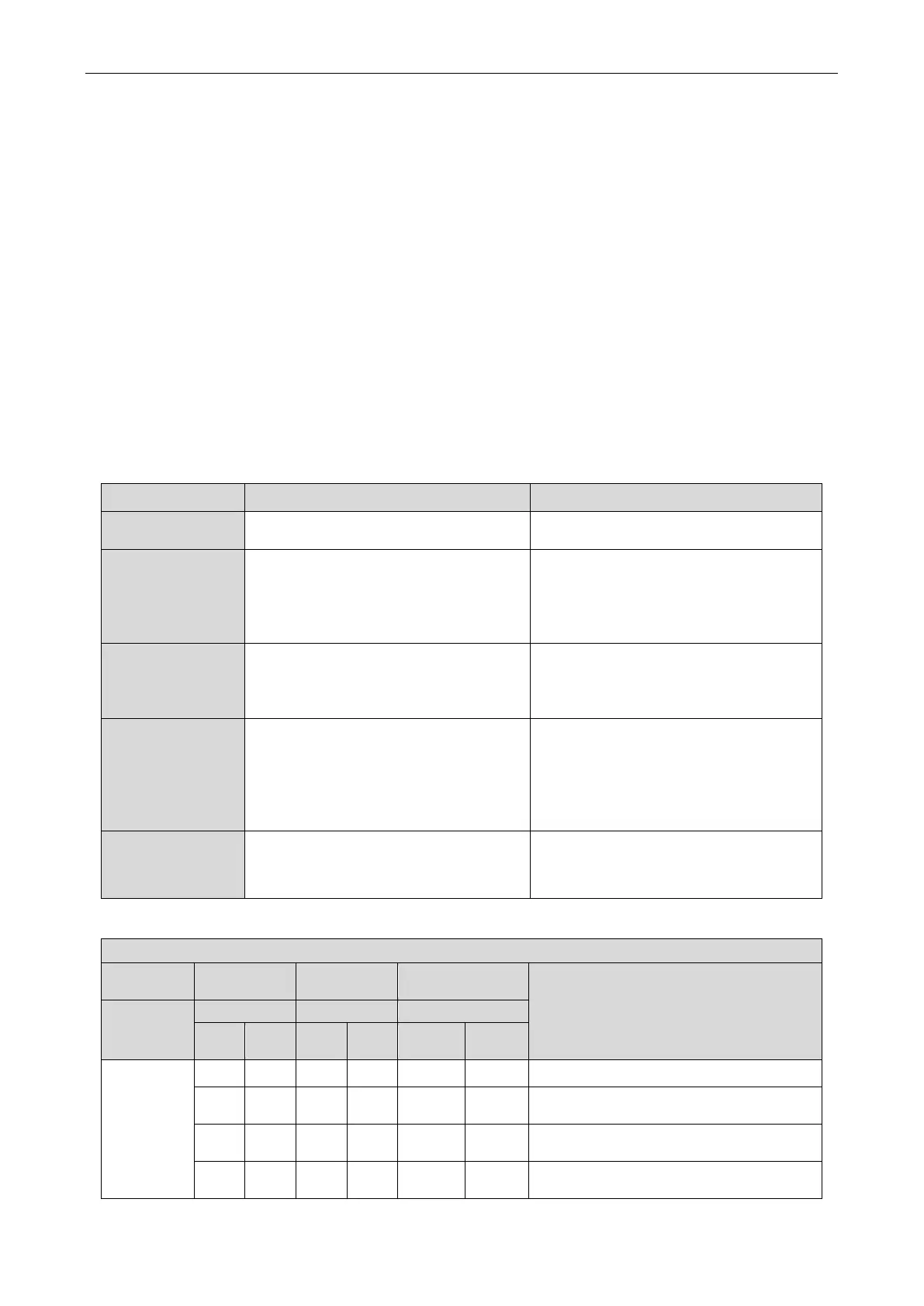
3.2.2.3 Display instruction for each stage progress at the time of debugging
Instruction for each stage progress at the time of debugging
—
Progress code Status code
Meaning
Progress
Code
Code
Code
01_
set up
master unit
db ON 01 ON A0 ON Undebugged status.
db ON 01 ON CC ON
The system hasn’t set master module. It needs
to reset it.
db ON 01 ON CF ON
The system has set more than 2 master
modules. It needs to reset it.
db ON 01 ON OC ON
Master module setting is succeeded. It will
automatically enter into the next step.
 Loading...